June 1, 2024 UPDATE:
Note: The current lead time for shipping LP-100A with LPC1 is approx. 2-3 weeks. Orders for LP-100A with LPC2 or LPC5 is a little longer.
Unbelieveable performance, sophisticated design, unheard of features. Simply the best!
More than 5,000 sold!
LP-100A is an industry standard reference power meter. More than two dozen are in use at major ham manufacturers' facilities for testing, checkout, calibration, etc. One is also used by the ARRL testing lab.


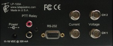
Rear panel shown with optional dual coupler board installed.
Plus, the LP-100A has additional modes no other wattmeter has when you desire them... vector impedance, dBm/RL, calibrated field strength and compression ratio.
Dual Coupler Option Two couplers... one LP-100A... auto-sensing... perfect for SO2R. Better than "paralleled" couplers because the couplers are isolated from each other, and each has its own Calibration table. Click link for details.

A truly unique and innovative design. We didn't just stick a digital
display on an old fashioned design. Compare
to any meter at any price! There is
nothing else like the LP-100A on the market. Please
take the time to read
this entire page (and links, including the extensive manual) for a
summary
of features and performance
data of this station monitoring and antenna measurement system.
The
graphic VFD display used in the LP-100A is the highest quality display
used in a digital wattmeter. It is manufactured in Japan by Noritake,
the
inventor of VFD, at their own facilities... not in China. In 10
years of production
of the LP-100A, we have not had a single display failure, or even a
report of wear. The quality and reliability of the display, combined
with unique screen saver options, adds up to a lifetime of enjoyment.
*
We
think you'll agree... the LP-100A is in a class by itself.
* Display note for
original
LP-100 (not "A") owners: We
have an inexpensive upgrade path to the LP-100A GVFD display (which
includes LP-100A firmware and features) for owners of the original
LP-100. In addition, we offer a very inexpensive OLED display
for original LP-100 owners who have experienced failure of their PLED
display. The new OLED display can be ordered in green or yellow and
is a drop-in replacement. It offers a quick and inexpensive
way for owners of the original LP-100 to extend the life of the meter
indefinitely, without changing the look or feel of the meter.
Standard
coupler is LPC1, 3KW PEP/CW**, 1.8 to 54 MHz.
Optional
couplers for ham use include...
LPC2 0.10W to 5KW CCS*, 1.8 to 30 MHz
LPC4 0.10W to 5KW PEP/CW**, 1.8 to
54 MHz 3KW PEP on 6 meters)
LPC5 0.20W to 10KW PEP/CW**, 1.8 to
30 MHz
*
CCS refers to continuous duty (key down).
** PEP/CW refers to 50% duty cycle typical of most ham modes.
Note: Allow up to a week delay for
orders with optional couplers.
LP-100A
standard configuration includes LPC1 coupler, 6' RF cables to connect
the coupler to the meter, 6' DC power cord (2.5mm ID / 5.5mm OD
connector, with tinned ends) to connect to 12VDC source with 500 mA
current rating. This can be your station power supply, rig 12VDC
accessory jack, "RigRunner" type DC power distribution panel or
dedicated power supply. A suitable wall mount DC supply can be used if
it is "clean", but most generate hash in the receiver. We are currently testing a couple that look promising, though.
 August 2007 QST Product Review
of
original LP-100.
August 2007 QST Product Review
of
original LP-100.Reprinted with permission of ARRL.
 Visit
eHam.net Product
Review page for LP-100 / LP-100A.
Visit
eHam.net Product
Review page for LP-100 / LP-100A.Documents and Manuals
Free Windows® Software - These programs extend LP-100A capabilities
Remote control/monitoring | Automated plotting of SWR, complex impedance, RL, rho, Smith Chart | Automated antenna pattern plotting | Integration with TRX-Manager
LP-100A Features & Specs
* Dual Coupler Option. Allows one LP-100A to use two couplers, with auto-sensing and switching to the active coupler.
Great for SO2R operation or when your transmit paths are different for HF and 6m
* Several new menus for additional customization of user preferences
* LP-100A now integrated with N4PY software
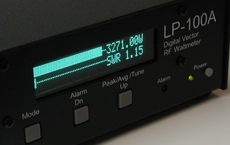
* Graphic VFD display with high contrast non-glare neutral density filter
* Front panel power switch
* Large scrolling call sign screen saver
* Setup screen for call sign entry
* Setup screen for display brightness
* Setup screen for screen saver timers
* Dual 40MHz Processors
* Per-band power calibration, user adjustable in 0.1% steps
* Frequency counter - user adjustable per-band corrections of all parameters.
* Only meter with Z, R, |X|, Phase display... not affected by local broadcast stations as antenna analyzers can be.
* Super wide autoranging power range of 50 mW to 3000W, 160-6m... perfect for QRPp through QRO
* Optional couplers for 5KW and 10KW.
* Only meter with Graphic VFD display. The graphic display allows for a solid bargraph with no gaps, and full screen scrolling screensaver as shown in the shot above with N8LP scrolling.
* Only meter with simultaneous bargraphs for Power and SWR (or Power and Ref Pwr).
* Highest bargraph resolution. 90 segments gives 1% tuning resolution with standard bargraph range settings (adjustable)
* Only meter that has a "sticky" bar to graphically show peak hold point even while bargraph is moving.
* Fast attack bargraph will accurately display a single "dit" at over 100 wpm. Decay adjustable for Fast, Med, Slow.
* Active temperature compensation. Only other meter with this is Alpha.
* True 12-bit A/D converter gives <1W resolution at 2000W. 13.6 bit effective resolution up to 360W.
* Return Loss (RL) display of 0 to 49.9 dB with bargraph
* Separate scale for dBm measurements, +15.0 dBm to +64.0 dBm with bargraph
* Field Strength input covers the range of -15 dBm to +33 dBm (0.04 mW to 2W)... great for beam pattern and bench measurements
* Peak to Average ratio screen. Allows accurate checking and setting of compression in your speech processor.
* Support within TRX-Manager for direct remote monitoring
* Call sign screen saver - user programmable
* Free Plot program displays SWR, Z, Phase, R+jX (including sign), reflection coefficient, Return Loss and Smith chart.
* SWR alarm with "snooze" mode for antenna tuning. Alarm has LED, PTT relay and audible sounder (which can be easily disabled)
* Separate coupler with 50 ohm ports for uncluttered desktop - remotable up to 50' with appropriate calibration.
* Three autotanging scales with independently adjustable maximums.
* SWR display resolution is .01
* SWR error < .15 (5%) from about 100mW to 3000W, <.05 typical
* Power accuracy is better than 5% at any frequency from ~1W to maximum, 3% typical with NIST traceable factory calibration
* Power display is actual power delivered to the load ( Fwd minus Ref power) or traditional Fwd power.
* SWR Alarm system with set points for Off, 1.5, 2.0. 2.5, 3.0 and user setting. Audible & visual alarm, with PTT loop-thru & adjustable power threshold
* Windows® freeware Virtual Control Panel for software control or remote control.
* Built-in bootloader to allow for firmware upgrades to be downloaded and installed.
* Conforms to FCC Part 15 A & B, ICAS and CE conducted and radiated emission limits, tested and verified by accredited lab
Basic setup and operation, along with full Setup menus and explanations of each. The LP-100 is highly customizable with 15 menus and over 70 choices. NOTE: Use the LP-100A Quick Start Guide, just below this, for LP-100A.
Quick Start Guide for LP-100A
Basic setup and operation, along with full Setup menus and explanations of each. The LP-100A is highly customizable with 15 menus and over 70 choices.
Quick Start Guide for LP-100A in German
German translation from our German dealer, Difona Communication.
LP-100A Operation Manual
Detailed setup and operation, including use of LP-100A software. Also includes circuit description, schematics, specifications and more.
LP-100 / LP-100A Users Group
Support and latest announcements. Open to prospective customers.
Digital Wattmeters and Pulsers
Link to QEX Article
Here is a link to the original QEX article on the LP-100. The article does not cover the R+jX display feature or any of the changes in the design required to add that feature, but has some interesting background design information.
Software
Download LP-100 / LP-100A software / firmware
Latest LP-100 / LP-100A firmware and Windows® software.
Virtual Control Panel (VCP)
The LP-100 Virtual Control Panel (VCP), below, is supplied free of charge. It allows for remote monitoring of the LP-100A's measurements. The mini-panel, shown running at W1MH's remote base station, allows for a simple display of power and SWR. The maxi-panel, not shown, also displays Z, R, X, and Phase, along with an entry box for your callsign, which is displayed in the LP-100A screen saver. To download the VCP, go to the LP-100-Update page. Click here to view the VCP help file.

________________________________________
Plot
Here are some comments on the Plot program since its release...
Great work on your Plot software. Another reason that the purchase of the LP-100 is a 'no brainer"!
I have been using LP-100 Plot, and it is an exciting software that mates perfectly with my Mark V Field. Now all my antennas have their SWR plots stored!
Did a plot on my 6m 5L in about 30 seconds after connection.
I really like the plot program. I have phased verticals for twenty meters and it showed me I should tune them for a little higher in the band.
Works great so far. I plotted my antenna in its old location, and will do it in the new one when I get my radials put down.
This plotting facility is absolutely fantastic. I am using an ICOM 756 Pro III so I connect plotter via HRD.
I did some plots on some of my antennas. A super program. Thanks much. I love the LP-100.
Below are reduced size screen grabs from alpha version 0.97 of the Plot program. This version has a nicer graphing component, than the earlier version I reported on. The Plot program can scan any frequencies, with sample spacings of 10, 25, 50, 100, 250 or 500 kHz. It displays...
R+jX
Z magnitude and phase
SWR
reflection coefficient
Return Loss
Smith chart
Power (dBm) (shown on the Plot samples page)
I still plan a lot of new functionality for the Smith Chart, like display of constant SWR circles, and adding beginning and ending frequency tags. Eventually I also want to add the ability to transform impedance, measure transmission lines for distance to fault, etc.
Plot uses a variety of methods to control the transmitter. Direct control of Kenwood and Elecraft K2 are provided, as well as transparent linking to three popular rig control / logging programs... TRX-Manager, Ham Radio Deluxe (HRD) and DXLabs' Commander. These programs are either free or inexpensive. I expect to provide direct control of Icom rigs as well, but the big advantage of linking to existing programs is that almost any radio that has a CAT interface can be controlled.
Version 0.96 offers smooth Spline interpolation and a two-pass automatic sign detection for Reactance and phase angle of Z. The sign detection algorithm uses a combination of Z and Phase slopes to determine proper phase sign, but it breaks down a little when the Z is broad and flat. To address it, I have included the ability to edit the curves. After a plot, it is pretty obvious from looking at the Phase curve where a mistake has been made. The plot can be fixed by clicking on a bad point... it will automatically reverse sign. Once the curve is fixed, you can save and/or print the corrected curve. Editing is allowed on all plots which involve sign, including R+jX, Z/Phase and the Smith Chart. Editing any of these corrects the source table so that the result ripples across the screens.


Click here for more screen grabs of Plots. Included are antenna plots of R+jX, SWR, RL, Smith and the newly added Power display. Also included are comparisons of Plot to my HP VNA with a 2-30 MHz sweep of a reactive load I use for calibrating the LP-100As, and with a pi-net filter. The filter demonstrates the versatility of the LP-100A and Plot program. It shows the power response of a homebrew low pass filter, as well as the input impedance when terminated with a 50 ohm load.
The new Power display is an important addition to the Plot program. This is a capability that no antenna analyzer has to my knowledge. Since they are all 1-port devices, they only allow reflection measurements. The LP-100A / Plot combo also allows transmission measurements, like a VNA. This allows placing a DUT (device under test) between the transmitter and LP-100A coupler, allowing power response measurements of filters and other frequency sensitive devices. Click here for more screen grabs of Plots.
Click for LP-100_Plot Help file.
Price List for US Orders Only:
After ordering, you will receive an immediate confirmation from PayPal, and a confirmation from TelePost within a few hours. If you don't receive a confirmation from TelePost, please email us to make sure that your order was received by us.
For orders outside US, please email us for price and delivery options.
US ONLY (for overseas orders, scroll down or click here)
| LP-100A: Includes standard LPC1 coupler (1.8 to54 MHz, 3KW), 6 ft. connecting cables between coupler and main unit, and power cable with tinned ends for connection to +12VDC. Also includes VCP, Plot and MCLoader software, 11 band NIST calibration and unlimited support of all software and firmware. |
$525.00
plus shipping
|
|
| Options
available for LP-100A at time of order. These options must be ordered
over the phone, or by email request. We can email a PayPal invoice to
you for payment. * High power couplers: Upgrade LPC1 to LPC2, LPC4 or LPC5... $75. Note: Upgrading a coupler that you already own requires that the meter be returned for modifications / recalibration at a cost to be determined by calling or emailing us. * Dual coupler board: $85 installed. Note: This board is also available for existing owners of LP-100A (not available for LP-100). Requires factory or user recalibration aftrer installation. * Additional couplers: LPC1, $150. LPC2, LPC4 or LPC5... $225. * N connectors: $50 per coupler. * Longer cables between coupler and meter: $1 for each foot of length over 6 feet (must be ordered with new meter since cable length affects calibration). * USB/Serial cable with FTDI chipset... $15 * 12VDC / 1A linear wall mounted power supply... $15 * Volume discounts |
Write,
call
or email us for a quote on orders with combinations of these options or
special requests. TelePost Inc. 49100 Pine Hill Dr. Plymouth, MI 48170 734.455.3716 |
|
Standard US flat rate shipping charge is $30 for UPS Ground or 2nd Day Air, Fedex Ground or USPS Priority Mail - 2 to 4 days, insured with online tracking. Shipping prices for custom orders may be higher due to additional weight and value.
You will receive an immediate confirmation from PayPal, and a confirmation from TelePost typically within a few hours with estimated shipping lead time. If you don't receive a confirmation from TelePost, please email us to make sure that your order was received by us.
Payment can also be made by credit card at 734-455-3716, or regular mail at:
TelePost Inc.
49100 Pine Hill Dr.
Plymouth, MI 48170
NOTE: PayPal orders are processed immediately, even if shipment is a few weeks away, which can happen between production runs. Credit card orders placed by phone won't be processed until shipment is imminent.
OVERSEAS ORDERS
Please email us for a quote. We offer USPS Priority Mail, UPS Worldwide Expedited, DHL Express Worldwide or Fedex International delivery. Please email us with your full address and phone number and we will quote your shipping options. Proper documentation is provided, including correct harmonized code to avoid duties where applicable.
Customs documents require an accurate value, and copies of the invoice. Please DO NOT ask us to falsify these documents!
LP-100A Assembled & Calibrated with LPC1... $525USD plus shipping
LP-100A Assembled & Calibrated with high power coupler (LPC2, LPC4 or LPC5)... $600USD plus shipping
LP-100A Assembled & Calibrated with Dual LPC1 couplers... $760USD plus shipping
LP-100A Assembled & Calibrated with LPC1 and 1 high power coupler... $835USD plus shipping
LP-100A Assembled & Calibrated with 2 high power couplers... $910USD plus shipping
___________________________________________________________________________________
Refer to the LP-100A manual for FCC, CE and Industry Canada compliance statements. All LP-100A parts and materials are lead-free, and represented to us as RoHS compliant by their respective manufacturers, distributors or dealers.