Pricing and specifications subject to change without notice.
USING
NaP3 With
LP-PAN
Installation, Setup and Operation Guide
NaP3 is a panadapter display program from Pete, F5VNB. It is an open source program running under the GNU General Public License v2 and is based on a combination of PowerSDR/IF* from WU2X and PowerSDR* v2.x.x from Flex Radio. It also offers some of the features of TRX-Pan, and adds a feature similar to the "Fixed" mode of the Elecraft P3. It is much streamlined compared to other flavors of PowerSDR*, and much simpler to install and set up.
I provide this page as a way to help users who want to use this program with LP-PAN. I have no official connection to Pete or the program other than offering suggestions and help with testing.
Image shown below is from NaP3 v4.0.0 RC1 (Release Candidate 1). This is the most stable 4.0 version (released June 7, 2014) and includes many new features including the ability to display telnet spots directly from various DX clusters, as well as spots broadcast from the telnet server in CW Skimmer. To jump to a spot, just click on the call sign. Other pictures on this page are from earlier versions, but will be updated soon.
Download this version here. Note: If you are running LP-Bridge or LPB2, you should use the latest releases, found here. Previous versions of all NaP3 and LP programs can be found in this folder, http://www.telepostinc.com/Files/
The pictures are reduced in size to fit on this page, with some loss of detail due to compression.

Above picture is NaP3 in
Collapsed mode. This mode allows most of the controls to be hidden. In
this example, the VFO, band and mode buttons are enabled, and the rest
hidden.
NaP3 will communicate directly with various rigs, including K3, Kenwood and recent Yaesu rigs (FT-950, 2000, 3000, 5000). It will also communicate with the rig through LP-Bridge or LPB2, which greatly extend the capability of the rig by allowing multiple applications to easily connect to the rig and share its serial port. LP-Bridge only supports Elecraft K3, while LPB2 works with all the rigs that NaP3 supports, including K3, plus it adds support for Elecraft K2. LPB2 has a couple minor limitations compared to LP-Bridge, but both should work well for most users.
Note: Pete has recently stopped development / support of NaP3, but aside from one minor bug, the program is still the best and most up to date SDR for use as an IF based panadapter. In the meantime, support questions can be posted to the LP-PAN User Group.
73,
Larry N8LP
*On this page and web site, all references to PowerSDR apply to FlexRadio Systems PowerSDRTM program. Support questions for the various PowerSDR based open source programs referenced here, should not be directed to FlexRadio Systems, but rather to the specific author of the modified version, or to N8LP, or the LP-PAN User Group.
NaP3 Installation
NaP3 Help
Rig Settings
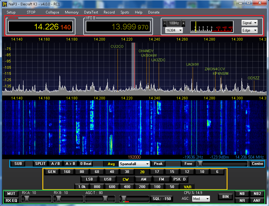
Above picture is NaP3 in Expanded mode. This mode shows all of the controls. Color overlays have been added to aid with the description of controls which follows.
Overview of Controls:
Refer to the above picture for a description of the controls. Color overlays are used to explain button functions by section. Carefully read the whole section because there are a number of not so obvious controls which are revealed as context menus when right clicking some of the buttons shown. The following section refers to the menu choices at the top of the NaP3 window.
Setup...
This pulldown menu has four choices...
Configure NaP3, allows detailed setup of all parameters, arranged into 8 different tabs. A thorough discussion of each tab is presented further down this page.
Equalizer, allows setting of the multiband equalizers for receive audio contouring.
Macro Commands, allows setting up of macros for user specific functions
Transverters, allows setup of the transverter band buttons.
RUN/STOP... Starts and stops processing of incoming data.
Collapse/Expand...
Toggles to the collapsed view which hides many of the controls and allows the pan window to fill the screen. Some of the other controls can be selectively added back based on the settings in the Options tab in Setup.
Memory... Allows user to set up multiple memories with 12 different paramaters per memory
DataText... Provides a window to display text from the K3 CW / Data text decoder
Record... Controls for digital recorder to record and playback entire screens on IQ audio data
Spots... Setup screen for telnet spots. These can come from well known web cluster telnet sites or from local telnet servers like the one in CW Skimmer.
Help... Comprehensive help file written by the NaP3 author, Pete, F5VNB.
Donate... Please consider a PayPal donation to Pete for all his hard work on this great program!
| RED SECTION |
VFO A, shows current rig main VFO frequency. Can be changed by entering a frequency, adjusting mousewheel or pointing and clicking in the display. Right clicking in the display will add yellow crosshairs. Placing the crosshairs over a signal and left clicking will cause the rig to jump to the signal. Right clicking again will turn off the crosshairs, or change them to red if SPLIT or SUB is on. Left clicking with the red crosshairs will cause VFO B to jump to the signal's frequency. Adjusting the mousewheel will fine tune. The frequency offset, signal level and absolute frequency of the crosshairs position is displayed below the pan window at the left of the screen in small blue letters..
Mousewheel tuning step size lets the user determine the rate of mousewheel tuning.
FFT samples, below mousewheel tuning step, allows setting the horizontal frequenct resolution of the panadapter spikes (FFT bins). The higher the number, the better the resolution as you zoom into narrower frequency spans. Note: Too high a number will bog down slow PCs, and display more extranneous household and neighborhood noises. These settings are saved per mode in the NaP3 band stacking memories.
VFO B, see VFO A explanation
S-Meter, can be set to read Avg or Signal, dBm or S-Units.
| BLUE SECTION |
This section constains the following buttons...
SUB... Turns the NaP3 sub-receiver on and off, and determines whether if follows VFO B as in SPlit operation, or acts as an independent third receiver if the rig already has a sub-RX. SUB must be on (and/or SPLIT) in order to see the second passband indicator in the display, and to enable mouse tuning of VFO B.
SPLIT, A/B, A>B, Zero Beat... Self explanatory. These control correspondingr functions of the rig.
AVG, display selector, Peak... The AVG button turns on averaging in the pan window to minimize noise. The display selector allows the user to select Panadapter, waterfall or a split-screen of both to fill the pan window. PEAK button causes the signals to accumulate at the highest level for each frequency bin. This is useful for spotting openings, especially on 6m/VHF/UHF. AVG and PEAK are dual functions buttons. AVG is also used to set the baseline noise level for each band, and the vertical range for each band. Hover over the AVG button with your mouse for directions. These adjustments are saved in NaP3's band stacking memories. PEAK works in a similar way for the waterfall minimum and maximum levels.
Free/Fixed, Zoom Slider, Centre... These control the behavior of the pan window. Free/Fixed toggles between free tune mode and fixed tune mode. In free tune mode, the IF center is always in the middle of the frequency display. In Fixed tune mode, the background is locked in one position and both VFOs can tune across the display independently. There are some limitations when the zoom is set to the maximum width in Fixed mode. The usable limits are greyed out in this case. The Zoom Slider allows the user to zoom from maximum display width (up to 192kHz depending on sound card) to minimum (as narrow as 1kHz or less). Centre recenters the display in Fixed mode. The Free/Fixed button is also used to adjust the ratio of panadapter to waterfall window proportions in a similar way that AVG and PEAK are used to adjust the levels. Hover over Free/Fixed for tool tips.
| YELLOW SECTION |
This section contains the Band, Mode and Filter buttons. The control the corresponding functions of the rig. Depending on the rig, you may or may not be able to set the exact filter widths shown. You can change these buttons to match your rig. Please see the author's help file for more details about filters, and for details about how the filter buttons interact with various rigs. Band buttons can display transverter bands if you set up transverters.
| GREEN SECTION |
MUT, mutes the audio output of the software (sound card).
RX EQ On/Off, enables the EQ settings that are set in the equalizer. The equalizer itself can be accessed by selecting Equalizer in the menu bar.
RX A and RX B audio gain controls, are used to adjust the audio output levels of the main and sub receivers. A, feeds the left channel and B, feeds right channel of your sound card outputs. When the subreceiver is not enabled, or SPLIT is not enabled, RX A feeds both outputs.
AGC-T (threshold), works like the RF gain control on a real radio. Sets the threshold where AGC action starts. Defaults to 80.
Squelch On/Off and Threshold, works like a normal squelch. Pressing the button turns it on. Sliding the slider adjusts the threshold. The little S-Meter below the slider aids in setting the threshold. Used mostly for FM.
CPU... shows the percentage of CPU power being used by your system. Anything consistently under about 70 - 80% is fine. Most modern PCs will be below 20%.
AGC... AGC hold time.
BIN, binaural mode. Creates a stereo field of signals based on frequency and phase to position signals between the user's ears.
NB / NB2, turns on digital noise blankers. Extensive settings for these can be found on the DSP tab in Setup. This control, and the following four controls do not change any parameters in the rig. These affect the audio output of NaP3, as heard on the sound card speakers/headphones.
NR, turns on digital noise reduction. Extensive settings for this are found on the DSP tab in Setup.
ANF, automatic notch filter. Automatically detects and notches out the strongest offending carrier in the passband. Extensive settings for this are found on the DSP tab in Setup.
--------------------------------------------------------------------------------------------------------------------------------------------------------------------------------------------------------
Fixed Mode...
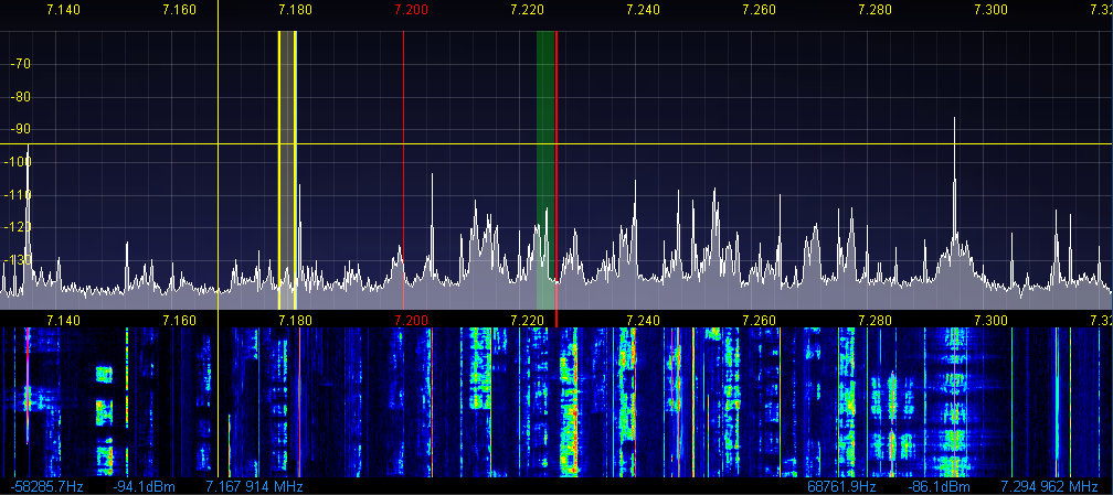
Above
picture shows a section of NaP3 pan
in Fixed mode, which locks the background in place while allowing the
two VFOs to be tuned separately over the background. Filter overlays
for VFO A Main (green) and VFO B Sub (yellow) are also shown. They are
currently only fully linked to the rig if it's a K3, but support for
the other rigs is in the works. Also shown is VFO B transmit
cursor
in split operation (yellow lines). The yellow crosshairs indicate the
mouse cursor position. They change to red when adjusting VFO B. Note: Some of the colors have been
changed in Setup from the defaults.
The blue numbers below and at the left side of the window represent the frequency offset, signal level and absolute frequency of the crosshairs position. The ones at the right side represent the frequency offset, signal level and absolute frequency of the strongest signal in the window.
The blue numbers below and at the left side of the window represent the frequency offset, signal level and absolute frequency of the crosshairs position. The ones at the right side represent the frequency offset, signal level and absolute frequency of the strongest signal in the window.
_____________________________________________
NaP3 Installation
The latest "stable" version is v4.0.0 RC1 (as of June 7, 2014), and is available here. There is a known bug in this version. When using RC1, set the Band Plan under the Display tab to Region 1 before running (even if you're not in Region 1). This will avoid an error which replaces the pan window with a large red X. Pete has recently ceased development / support of NaP3, so it is not known when or if this bug will be fixed. Even with this minor bug, NaP3 is by far the best SDR app for use as an IF based panadapter. Operational support is available from a number of outside user groups, including the LP-PAN User Group.
Note: When changing between major version releases (like from v3.x.x to v4.x.x), you need to reset the database, or delete it. This is because the format of the file has changed over time to accommodate expanded capabilities. The database file is called NaP3.xml, and is located in your C:\Users\<your user name>\AppData\Roaming\NaP3 folder. Your user preferences and settings will be lost, so you must write them down before doing this.
Note: If you are running LP-Bridge or LPB2, you will also need to upgrade those. K3 users should update LP-Bridge to v1.08 to take advantage of all the new features of NaP3, http://www.telepostinc.com/Files/LP-Bridge_108_update.zip . You will have to update to the full version v1.07 first, http://www.telepostinc.com/Files/LP-Bridge_107_full.zip .
For non-K3 users, the latest version is v1.06 full, http://www.telepostinc.com/Files/LPB2_106_full.zip
Note: Be advised that the new versions all use the latest Eltima drivers, which makes loading of LPB slower than the older versions, but makes them windows 8 compatible.
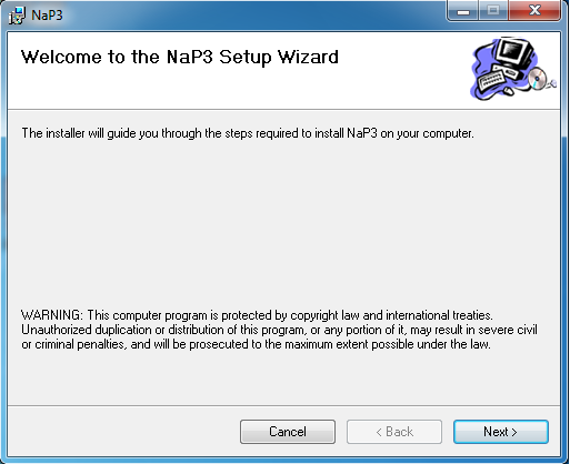
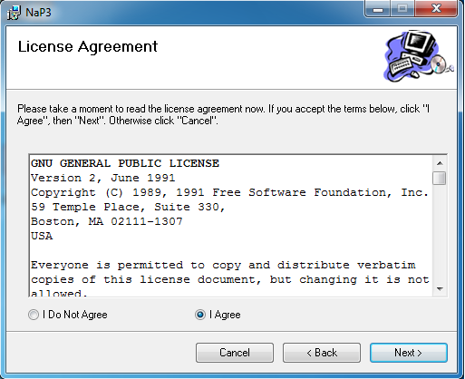
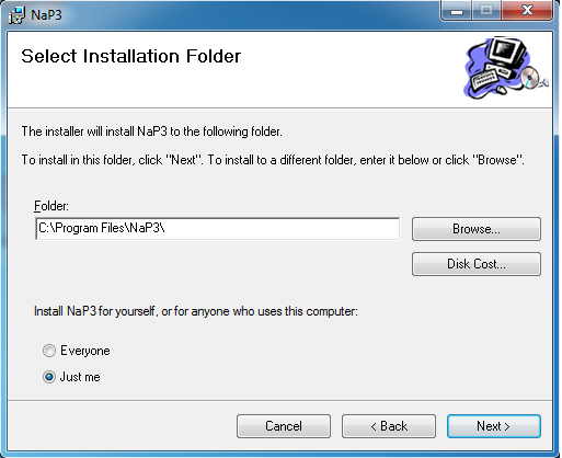
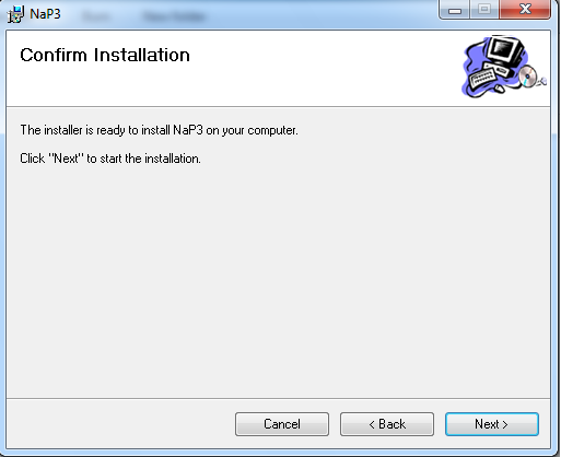
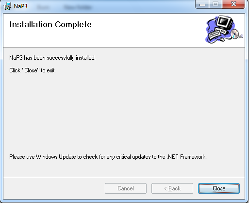
Unzip the folder and run the Setup.exe or Setup.msi file. You will see the following screens during installation...
Follow the directions and accept all the defaults. Note: If you already have a version of NaP3 installed, you will see an additional screen which will ask you if you want to repair or remove the existing version. If asked about replacing an existing file with an older one, always keep the newer file. When asked whether to allow access to the program to "Everyone" or "Just Me", your choice will affect access to the program and the path to where the database files ( with all the settings) will be placed. With Everyone it will be placed in your Users\AllUsers\AppData\ path. With "Just Me" it will be placed in your Users\<your username>\AppData path. To avoid confusion, we recommend the "Just Me" choice.
 |
 |
 |
 |
 |
 |
After closing Setup and launching the program for the first time, it will run a one time check of forward and reverse FFTs. Here's a picture of the screen you will see during this process...
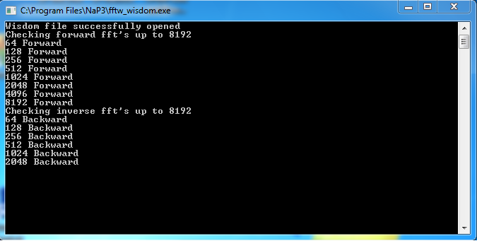
Just click OK to close the warning screen that accompanies this. When it finsihes, the program will start. Proceed to the next section for initial setup.
_____________________________________________
NaP3 Help -
Click to open NaP3 Help in Windows Help format... NaP3 RC2_Help.chm
This version is a little newer than the help file in NaP3 v4.0.0 RC1, and includes help on the Spots feature. You can access this directly by clicking on the link and selecting Save File. Navigate to the saved folder and open it. Click on the NaP3_Help.chm file to view the help. For convenience, you can create a shortcut to this file and put it on your desktop. I have also created a simple pdf of the same info, but the formatting is not nearly as nice, NaP3_RC2_Help.pdf. The document will look much cleaner if you save it to your desktop and open it from there, rather than opening it directly from the link. The chm file is much preferred.
Restoring lost Spots window...
If the spots window does not appear when you click on Spots, it is because it is off screen somewhere. To restore it, use this trick. Hover over the NaP3 icon in the Taskbar. Slide your mouse pointer up to the small version of the Spots window and right click. Then chose the Move option and left click. If you now press any arrow key, the window will appear and can be moved with the mouse. Note: Once the window is back, you can right click in any free space in the window and will see some options. One of the options is Autostart. If you click on Autostart, the spots program will start whenever you start NaP3. You won't need to use the spots window again unless you want to change the settings.
This help file covers the important settings in NaP3. After successfully getting things going, you can adjust the IF Frequency Offsets as shown in the pictures below to fine tune the signal positions withing the display. This is required for all rigs except the K3, which reports this information to NaP3 using special CAT commands.
Rig Settings
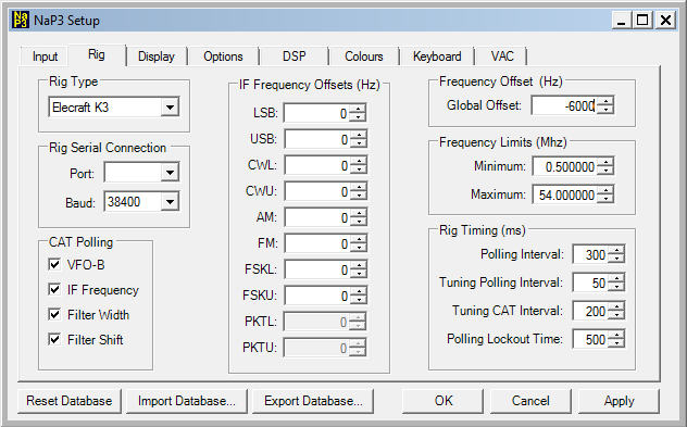
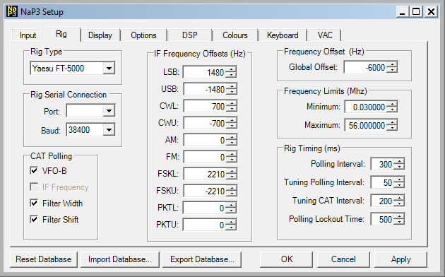
Here are examples of the rig setup tab entries for the most popular rigs (K3 and FTdx3000/5000). In addition to the settings shown, you need to select the proper com port for your rig. The filter width and shift boxes should only be checked if you wish to have the SDR filters track the rig filters. To use the SDR filters independently, leave these unchecked. Baud rate should be the fastest that the rig allows. Make sure that the rig is set for the same baud rate that you select here. PSK settings are not shown for the Yaesu rigs are shown as "0", but probably need to be some other value. Check with Yaesu owners on the LP-PAN user group.
Values for other rigs will be similar to the FTdx3000/5000 settings, with the exception that for the FT-950/2000, you will need to reverse the audio cables or the IQ channel settings because the IF-2000 interface boards inverts the passband.
What do these figures mean, why are they here and how are they fine tuned?
All transceivers use a carrier offset in most modes (except AM and FM). This is inherent in the design of transceivers, since regardless of mode, the rig must provide a BFO signal that produces a demodulated signal with the proper pitch. Each manufacturer uses different values, but they fall in a general range of about +/- 1500 Hz for SSB, and +/- 300-800 Hz in CW (the CW offset matches your rig's "sidetone pitch" setting). As stated before, the K3 sends this offset data to NaP3 via special CAT commands, so the user does not need to enter anything.
The Global Offset is due to an intentional IF offset built into LP-PAN / LP-PAN 2. Unless you have a very old LP-PAN, the offset is -6000 (negative 6000 Hz). This moves any sound card anomalies such as DC offset, hum and noise away from the tuned frequency.
When adjusting the offsets, enter the values shown. These will generally be within 100Hz or so of optimum. To fine tune, start with AM. Tune your rig to a known broadcast station such as WWV or a local AM station. Set the rig for EXACTLY the station's frequency. Examples would be 10.000.000 (WWV), or 760.000 (WJR, Detroit... my strongest local station). The carrier should be exactly on the red centerline in the pan display. If not, slightly adjust the Global Offset until it is. Zooming into the display will make it easier to see any positioning error. Increasing the FFT size(in the S-Meter section of the main display) will provide even more resolution.
If you are only using NaP3 as a visual display, this is all you need to do. If you plan to also listen to the demodulated audio from NaP3, you will have to fine tune your other modes by comparing the pitch from your PC speakers to the pitch from your rig in each mode. I find that listening to AM broadcast band or SW stations thru NaP3 gives much better fidelity than listening thru the rig speakers. In some cases, the DSP controls in NaP3 will also outperform the rig, especially the noise blankers which are highly configurable.
If the sidebands sound inverted, or the adjustment work backwards, you will probably have to reverse your audio cables, or click Swap IQ on the Input tab in Setup.
