LP-StepLink is a freeware application that gets transmit freq data from TRX-Manager through OLE or Commander from DXLabs through DDE, and then relays it to the SteppIR control box by "emulating" a Kenwood radio over a computer serial port. This allows connecting any rig supported by TRX-Manager or Commander to SteppIR with a consistent interface, and at the same time allows computer control and logging. The antenna tuning follows freq adjustments either at the rig, or from the logging program. This program can run in the background, and the only input from the user is to specify the com port the SteppIR box is connected to and the source program for frequency.
Unlike using a Y cable to control the SteppIR, using LP-StepLink has several advantages...
Simple one-cable interface.
Use with any rig supported by the logging programs
Allows the SteppIR to be controlled by multiple rigs by following the
rig selection in the logging program
Fixes retuning of SteppIR in split mode by only supplying transmit
frequency to the SteppIR
Adds hysteresis to prevent SteppIR from retuning constantly at the
middle of the SteppIR 50 kHz tuning windows
LP-StepLink works with any SteppIR antenna including the verticals, and MonstIR. All that is required is a 3-wire female-to-female null modem serial cable and a spare COM port on your computer. Shown below are LP-StepLink normal and setup windows.
For more information, check out....LP-StepLink Help.
LP-StepLink ver. 1.1 is available for download on the Downloads
page.
SteppIR
Virtual Control Panel (for old controller). Scroll down for information
on SteppIRVCP for SDA100 controller.
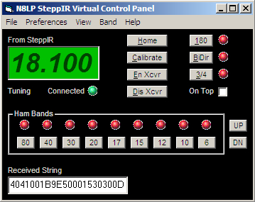
In response to recent changes in the serial interface on the SteppIR controller, I have created a software Virtual Control Panel (VCP) which will allow control of the supported serial control functions on the SteppIR controller. These functions include...
Set Frequency
Set Direction (Normal, 180, Bi-Directional, 3/4
wave)
Home
Calibrate
Enable xcvr interface
Disable xcvr interface
Frequency Status
Direction Status
Motor Activity Status
There are three "views" available for the program. The compact view shown above, the diagnostic view that's shown below and a full view that looks like the diagnostic view without the Received String window. The diagnsotic view shows the hex responses from the controller for troubleshooting. To keep things familiar, I chose to copy the basic SteppIR controller with a few exceptions. Because of the way commands are implemented, I was able to change the 180 and Bi-Dir to two separate buttons to eliminate the need to cycle through Bi-Dir when reversing the beam. I also used a more visible red TUNING indicator as opposed to an asterisk.

The SteppIR VCP always shows the current status of the SteppIR it's
controlling. When new frequencies are sent to the controller, or when
functions such as 180, Bi-Dir and
3/4
are sent, the status LED indicators only change when the command has
been
received and accepted.
The Setup screen allows selection of com port, baud rate, status polling rate and antenna type. The antenna type determines the allowable tuning range of frequencies sent to the controller. When sending frequency data to the SteppIR controller's DataOut port, strange frequencies can wind up being displayed if they are outside the controllers design range. No SteppIR currently tunes 80m, but a future option for the BiggIR will include this feature.
For more detail, check out the N8LP SteppIR VCP help file. To download the SteppIR VCP go to the downloads page.