N8LP E-Beam Hybrid Active Phased Array
The N8LP E-Beam is a unique hybrid design that acts as a broadband active phased array in receive, and a narrowband parasitic array in transmit. A carefully designed broadband phasing network is used in receive, while in transmit, a PIC microcontroller is used to adjust element tuning and matching, automatically, within 50 KHz. The beam features two 14' fan elements and a boom length of 8.5'. Predicted performance is what would be expected on transmit from an efficient 2-element Yagi that can be fine-tuned within 50 KHz of the operating frequency. On receive, the predicted directivity is equivalent to a 3-element Yagi, or more appropriately a large LPDA, since this directivity is available on any frequency in the HF spectrum, without adjustment.
The idea of a hybrid design grew out of my desire for better performance than a 2 element parasitic yagi on a fixed-length boom can provide in terms of F/B. Even with realtime monitoring of reflector phase and gain, and computer control of the reflector tuning, the best F/B ratio that can theoretically be obtained with a two element parasitic design is about 20 dB on 20 meters, dropping to 10 dB on 10 meters. Good gain is easily obtainable on all bands, however. By separating transmit and receive functions, it becomes possible to optimize the performance for each. A great pattern is not necessary for transmitting...all that is needed is good gain. My design uses a standard relay-switched L-network to match the DE... a unique arrangement is used to tune the reflector which provides very low loss and high reliablility, while allowing fast tuning within a few kHz of optimum.
On the receive side, in order to obtain a radical improvement in F/B ratio, I determined early on that a totally phased array would be needed. This turned out to be an absolute nightmare, since the mutual coupling between elements makes it impossible to get a proper match for the phasing lines over more than a very narrow frequency range. Through extensive modeling and careful design of broadbanding element loading circuits, I was able to reduce the effects of mutual coupling to an insignificant level. This in turn allowed precise and predictable phasing and matching of the elements. Because of the losses in the broadbanding circuitry, however, it was necessary to design an active phasing circuit that had high gain and low noise.
I spent a great deal of time optimizing the phaser for phase linearity and gain flatness, with the goal of very good broadband F/B performance with one setting of phase and gain. The phaser shows a consistent null of over 40 db from 5-35 MHz using a test jig with the same phase delay as the beam. For flexibility and operating convenience for DX'ing and net operation, I have provided instant forward/reverse direction switching.
Noise Figure was an important aspect of the design, since low noise and high gain are required to overcome the losses of the broadbanding circuits while providing a system noise floor below external atmospheric and man-made noise levels. At the same time, IMD products have to be kept below the noise floor to be competitive with passive beam designs. The N8LP E-Beam achieves these goals with a noise floor below the external noise levels on all HF frequencies from at least 7-30 MHz, and with IMD products below the noise floor for signals 20 dB above those typically seen in the HF bands.
On the transmit side, after playing with both commercial and homebrew autotuners, I decided on a semi-automatic tuner/memory system to allow for matching of the DE and tuning of the reflector. The user stores L-network and reflector tuning settings during a one-time setup routine, and saves the settings in frequency-specific memories. The idea of a semi-automatic system eliminates the relay chatter and possible retuning of an autotuner. By manually setting the memories, the user can adjust for actual conditions at his location as opposed to using factory presets that would assume certain environmental conditions.
The tuning process involves simply setting the L-network for minimum SWR, and the Reflector tuning for maximum reading on the "Gain" bar-graph display. The PIC receives current samples from both elements and develops a composite indication that is proportional to gain. Memories are provided every 50 kHz on 20m, every 100 kHz through 12m, and every 200 kHz on 10m. The PIC has a built-in counter which determines the operating frequency and automatically selects the correct memory. If the frequency is between memories, the L-network settings from the closest memory are used, and the Reflector tuning is interpolated from the two closest memories. Reflector tuning is continuosly adjustable in ~10 kHz increments. Worst-case tuning time is .25sec from 13.6 to 30 MHz. A 20x2 LCD readout is provided to show memory settings for C, L and Ref settings. It also displays frequency and a tuning bar-graph for gain peaking. LEDs are provided for power, tuning and T/R indication.
Below are performance curves of the E-Beam in receive, showing the theoretical receive pattern at midband (20 MHz), with graphs of gain, F/B, F/R and SWR over the design range of 10-30 MHz. These graphs were developed using the MultiNEC program, which allows for custom sweeps and graphs to be developed in Excel, using a number of popular NEC "engines". The pattern is virtually the same at any frequency in the range. Of course, directivity and not power gain is the important factor as long as the noise floor of the antenna system remains below the atmospheric and man-made noise, as mentioned earlier.
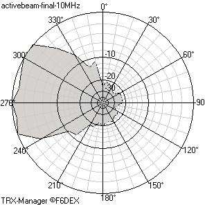
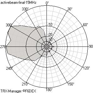
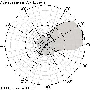
Shown below are off-the-air plots of the N8LP E-Beam at 10, 15 and 25 MHz using WWV and a commercial broadcast station as signal sources. The plots were created with a combination of my LP-Plot signal capture utility, and the TRX-Meter utility supplied with the excellent TRX-Manager rig control/logging program (www.trx-manager.com). LP-Plot controls the rotator and reads S-meter values from the rig through TRX-Manager's OLE interface, and integrates ten readings per 10 degree step and normalizes the readings. Importing the data log into TRX-Meter then allows nice azimuthal displays to be made. I made three runs for each plot and averaged them to reduce the effects of fading.


As can be seen from the above off-air results, this little mini-beam truly has maxi-beam performance over a wide frequency range, with no adjustments required. Switching from Front to Back when pointed directly at a station typically produces a change of 6-8 S-units on my calibrated rig, which equates to ~30 dB.
Even though I designed it as a 10-30 MHz antenna, the E-Beam provides very good receive performance down to 7 MHz, and useable F/B down to 3.5 MHz, although the signal output level would be considerably lower than a full-size antenna at that frequency. Doubling the size of the elements and boom would allow the E-Beam to work efficiently down to 80 meters, with quite useable performance on 160 meters... but the upper frequency would be reduced to 14 MHz, since the working bandwidth for transmit is limited to a range of about 4:1. With its directivity and quiet noise levels, this should make an excellent DX antenna for the low bands.
The E-Beam is built on four printed circuit boards. One main board is required for receiving...the phaser board. Three boards are required for transmit...the microcontroller board and two element tuning boards. For receive only, the two element tuning boards are replaced with small broadband matching boards.
Here are the theoretical specifications of the N8LP E-Beam, including actual results of on-air testing for the receive portions.
System Specs
Transmit frequencies - 14-30 MHz
Transmit gain
-
5.8 - 7.5 dBi
Power handling
-
500 W
SWR
1.5:1 or better, 14-30 MHz continuous coverage
Tuning time
-
.25 seconds maximum
Receive frequencies - 3.5-35
MHz
Receive directivity
-
~8 dBi
Receive F/B
Ratio-
25-35 dB typical
Reverse switching
-
Instantaneous in receive, not electrically reversible in transmit.
Element length
-
15 feet
Boom length
-
8.5 feet
Weight
Approx. 15 lbs. - easily turned by a "tv" type rotator.
Interface
Windows software control panel or self-contained PIC based
microcontroller.
Phaser Specs
Gain
-
23 db maximum, gain inversely proportional to frequency
NF
-
4.5 db overall
1 db compression point - +5 dbm at phaser inputs ( +10
to +30dbm at the elements)
Input IP3
-
+20 dbm ( +25 to +45dbm at the elements)