Detailed Specs & Performance Measurements
Specs:
LP-PAN is a software defined IQ direct conversion receiver with integrated SDR application to provide a high quality panadapter to rigs with IF output jacks. The unit uses a combination of SMT and through-hole technology, a custom aluminum case with powder coated finish and silk-screening. Pricing for an assembled and tested unit is $225 plus shipping, and a kit is available for $175 with SMT parts pre-installed. The kit takes an average builder about 2 hours to complete, plus another few minutes to adjust the front end filter. LP-PAN is aimed at the Elecraft K3, but can also be used with many earlier Kenwoods with IF output jacks, Yaesu FT950/2000/5000, as well as TenTec Orion and Elecraft K2 when modified to bring out the IF signal.
Here is a list of current features...
* Crystal controlled local oscillator for low phase noise.
* Up to 192 kHz display on PC, sound card dependent
* Switching quadrature detector for high dynamic range
* Strong buffer amp with very high LO isolation to protect K3.
* Ground isolated inputs / outputs with mil spec audio output xfmrs
* Fully balanced architecture with balanced and unbalanced outputs
* Jumperable ground lift on RF input and audio outputs
* Point and click frequency control with PowerSDR / IF Stage. In addition, LP-Bridge allows sharing of K3/LP-PAN with up to five loggers, PSK programs, CW-Skimmer, etc.
* Usable with many other SDR programs for basic panadapter display.
* Powder coated aluminum enclosure with silk screened graphics.
* Hardware or software mute
* Available for the following IF frequencies...
8.215 MHz (Elecraft K3)
8.83 MHz (most older Kenwoods)
9.00 MHz (Yaesu FTdx5000, TenTec Orion)
4.915 MHz (Elecraft K2)
10.7 MHz (IC-R8500/9500 and others)
10.55 MHz (FT-950/2000)
Orion & K2 require hardware modification to add an IF output port. IC-R8500/9500 require the addition of a blocking cap in the RF cable to LP-PAN. FT-950/2000 require IF-2000 interface board (see link above).
Here are current specifications (sound card dependent). Note: Measurements represent the composite results of K3 / LP-PAN. Standalone LP-PAN performance is even better.
* Approx. -125dBm MDS with K3 preamp on (about 8dB better with K3 buffer mod installed).
* +2dBm maximum input with K3 attenuator on
* ~105 to 115dBm dynamic range, depending on sound card
* 80-90dB image rejection with PowerSDR-IF
* Greater than +20dBm IP3 @ -15dBm, 2kHz to 20kHz spacing (composite value for K3/LP-PAN combo)
* ~90dB IMD DR @ -35dBm, 2kHz to 20kHz spacing (composite value for K3/LP-PAN combo)
* THD ~ 0.005%
* 600 ohm output Z, balanced or unbalanced.
* +2dBV (1.27 Vrms, 3.6V p-p) nominal output level at recommended maximum RF input
* Adjustable gain to interface almost any sound card
* L.O. offset to allow use with older sound cards
* 11-16 VDC @ 55 mA
Note: Specifications dependent on sound card, and subject to change. Cited values were taken with an E-MU 0202 USB sound card. All measurements also apply to M-Audio Audiophile 2496 PCI or FW cards (limited only by 96 kHz display width), the Infrasonic Quartet and E-MU 1212m PCI sound card. Measurement details are included in the Performance section below. PowerSDRTM is an open source application for use with IQ based software defined radios, and is a trademark of FlexRadio Systems.
Hardware:
LP-PAN consists of a multipole bandpass filter, followed by a strong buffer amplifier with high isolation, followed by a balanced switching mixer. The output of the mixer is fed to two pairs of balanced low noise op-amps with ultra wideband 600 ohm output transformers for flexibility in sound card interfacing. I have also tried to maximize interfacing flexibility with the sound card, to minimize hum and noise issues there. The devil is in the details, and that is where I have concentrated my efforts to make LP-PAN the best integrated panadapter solution for use with K3.
Software:
LP-PAN can be used with most SDR decoding applications, like PowerSDRTM, Rocky, SpectraVue, Spectrum Lab, TRX-Pan, etc. With NaP3, TRX-Pan or the /IF branch of PowerSDRTM and LP-Bridge, point and click frequency tuning is available. LP-PAN will also work with other programs which will decode an audio IQ signal, like the nifty CW Skimmer from Alex, VE3NEA. The pictures in the performance section below are taken from various flavors of PowerSDRTM.

LP-PAN allows you to use your PC / sound card as a second receiver with lots of nice features if you use the PowerSDRTM app. Shown above is split operation using the main and sub receivers in PowerSDR. VFO A (green) from the K3 is linked to the main receiver in PowerSDR, and VFO B (blue) is linked to the sub receiver. The K3 doesn't need the KRX3 2nd receiver option. PowerSDR provides both receivers. PowerSDRTM has lots of flexibility in terms of modes, bandwidths, interference reduction tools, etc. I find listening to SW broadcasts with the synchronous AM detector very nice.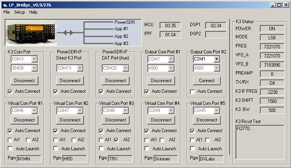
Performance:
Note: All test results were obtained using an E-MU 0202 USB sound card. Similar results can also be obtained with the E-MU 1212m or 1616m PCI cards, or the Infrasonic Quartet PCI card. At up to 96 kHz, the M-Audio Firewire Audiophile card (discontinued but available on eBay) or E-MU 2496 PCI card will also produce similar results. Except for the 1616m, these cards are all priced in the $80-150 range.
Performance is a composite of LP-PAN / K3 system unless otherwise noted.
Usable Dynamic Range:
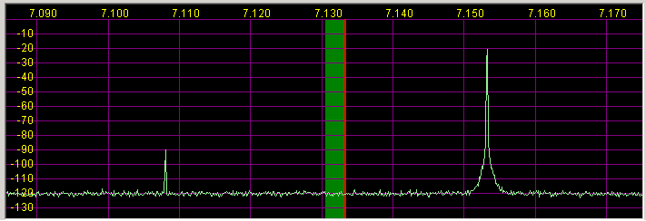
When connected to the K3, LP-PAN provides up to 115dB dynamic range between noise floor and clipping, depending on sound card. Below is an example of LP-PAN working with PowerSDRTM. There is no higher order distortion visible at a level of -20dBm (~ S9 + 53dB) from my HP-8640B signal generator at this bandwidth setting. 2nd harmonic, not shown, is about 80dB down. Increasing the level to -10 dBm (~ S9 + 63dB), about 5 dB before clipping, a couple small distortion products appear about 10-15 dB above the noise floor. The average noise floor is about -120 dBm (~0.2uV for 10dB S/N) in this setup. This test was run with the K3 preamp OFF. Noise floor with the preamp ON is about 10dB better. The smaller blip is the image, which is 70dB down (Image Rejection with PowerSDR-IF v1.19.34 has improved to >80dB).
Image
Rejection:
The above display shows typical image rejection with older version of PowerSDR-IF. The latest version, v1.19.35, uses the new Wide Band Image rejection (WBIR) feature of PowerSDR, and provides image rejection of 80-90dB or better over the entire display, with no user adjustment. WBIR "learns" the correct values and saves the parameters in a database file. This means that a signal of S9 + 30dB to S9 + 40dB will have no visible images. More information regarding image rejection can be found on the SOundcards web page, http://www.telepostinc.com/soundcards.html
Spurs:
There are many reasons why a user might see spurious signals in his display.
Many of them, if not most of them, are stray signals from local noise sources around the home and neighborhood. Some come from the shack in the form of noise from a PC, serial or USB cables, switching power supplies, etc. These signals can be picked up in the cabling between LP-PAN and the rig, power supply or sound card. In general, if the spurs don't change with band changes, they would fall into the category of locally generated noise entering through connecting cables. Careful grounding, selection of well filtered power supplies and use of high quality shielded cables should eliminate these.
Some spurs may actually be radio signals that are unidentifiable. These would change with bands and band conditions.
And some can be generated in the rig itself in the form of images generated in the rig's front end and spurs generated by the rig's synthesizer. Since LP-PAN is generally fed by a buffered output of the rig's 1st mixer, any strong image signal getting through the rig's front end filter can cause a spur. Also, unwanted signals from the synthesizer chain can mix with desired or image signals, or just be passed through to the mixer output. Note that you may see spurs from on the rig's IF output port that you can't hear on the rigs audio output. Since synthesizer spurs can be calulcated, manufacturers can use digital wizardry to blank out the spurs in the DSP processor which is downstream of the IF output.
The RBW (Resolution Band Width) setting in the SDR application can also affect what you see. RBW is defined as the smallest frequency interval that the software can display, and is determined by the total bandwidth of the display and the number of samples (or FFT bins) that are used across the display. In PowerSDR/IF the RBW is a fixed value dependent only on the sound card sampling rate. The number of bins is 4K (4,096), and the sampling rate is usually 192kHz, but can also be set to 48kHz or 96kHz. At 192 kHz sampling rate, each bin represents a frequency change of ~48Hz. Many spurs can fall between steps this large. In NaP3, the user can select up to 64K FFT samples. Frequency changes are thus 16X smaller, or 3Hz. Clearly, it would be harder for a spur to hide with this kind of resolution. The question is, how much RBW is enough. Most users should find that 16K FFT samples would be more than enough except possibly at the narrowest of displays spans (below 10kHz). Below are pictures of the 6m band at N8LP with a span of 80kHz and various conditions as captioned.

Blocking Dynamic range (BDR):
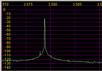
I wanted to make sure that the K3 was the limiting factor when used with LP-PAN, at least up to the maximum signal level of LP-PAN, which is +2dBm (S9+75dB). To test the BDR performance of the LP-PAN / PowerSDRTM combo, I set up the following test...
I fed a strong signal (S9+50dB) to the K3 using a homebrew xtal oscillator which has very low phase noise. 2kHz away I mixed in a 3uV signal from my HP-8640B signal generator using a hybrid combiner. The widening of the base of the signal from the xtal oscillator is due to the phase noise of the K3. I purposely used a xtal local oscillator for LP-PAN to minimize phase noise degradation. The 3uV signal in this case has about 10dB SNR, more than enough for solid copy. In practice, this situation would never occur since most transmitters are far noisier than my xtal generator, and the transmitter noise would bury any weak signal 2 kHz away. Receiver design has clearly advanced to the point where it far exceeds transmitter design.
IMD Dynamic Range:
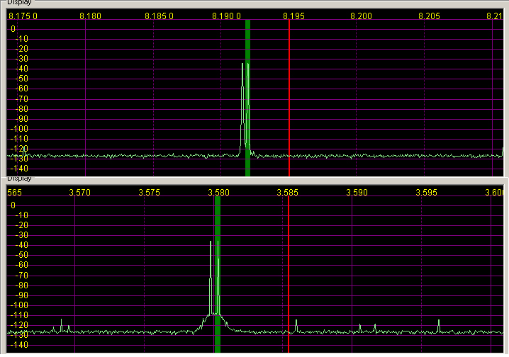
Here is a comparison of IMD DR with the standalone LP-PAN, and through the K3. The setup is the same as the one for the BDR test above, except that both the xtal oscillator and the HP-8640B are set to the same level. Signal levels are -33dBm (S9 + 40dB), and signal spacing is an amazing 500Hz! The slightly wider signal on the left is the HP, but it's still excellent phase noise performance compared to today's synthesized generators, and stands up well against the xtal oscillator. As you can see in the top picture for the standalone LP-PAN, IMD DR is >90dB, with no extraneous distortion products. Quite amazing for this bandwidth.
The bottom picture was taken with the K3 in line, with the K3 preamp Off. You can readily see the effect of the K3 phase noise by comparison. Reciprocal mixing with the K3 synthesizer noise sidebands produces a noise hump around the signals. This is actually excellent performance for a synthesizer, but clearly degrades close-in dynamic range. We have also picked up some minor blips.
L.O. leakage / isolation:
Because LP-PAN connects to an unprotected IF port on the radio, it is important that any LO leakage in the rig's passband be very low. This is something I spent a lot of time on in design and testing. As a result, the measured LO signal at the input of LP-PAN is -135dBm (~0.05uV). Adding in an estimated 20dB+ isolation for the buffer in the K3, this should be a more than adequate amount of isolation to prevent any issues with the K3. In my initial testing, I have not been able to detect LP-PAN's LO in my K3, confirming that the leakage is below the noise floor of the K3. For comparison, the LO leakage of a couple SoftRock receivers that Jack, K8ZOA and I checked, measured about -40dBm (S9+33dB)... almost 100dB higher than the buffered LP-PAN.
I also added more filtering to the input of LP-PAN to filter out the numerous spurious signals I found in the K3 IF output. These signals include LO leakage from the K3, plus harmonics and mixing products of them. The picture on the left shows the K3 IF output with one signal in the passband over an 80 MHz span. The second picture shows the same conditions with my filter installed. In practice, I see a number of products sliding through the panadapter display as I tune without the filter, but none with it.
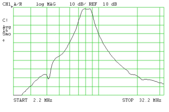
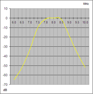
Here is the response of a
breadboarded version
of the filter. I could probably reduce the bandwidth, but at the
expense of loss and ease of tuning.The K3 already has more loss than I
would like from antenna jack to IF output, and I am being careful not
to add to it. I think this filter is appropriate for
the application, and is more tolerant of component variations. I use
variable caps and 2% precision SMD coils in the filter, and
tuning is just a simple matter of peaking the two variable caps.
Audio
Interfacing:
To minimize installation problems, I added transformer coupling of the IF port and mil spec audio xfmrs, all with "ground lift" jumpers to minimize hum and noise in the audio interface. Audio output is 600 ohms to allow driving any sound card, and one channel has an adjustable load to balance out any termination variations in the sound card / cabling. This level of detail is required to acheive the image rejection that we are able to get, which rivals a superhet with xtal filtering when carefully adjusted. The outputs can also be used in either balanced or unbalanced mode for further isolation when a professional sound card with balanced inputs is available. As the PowerSDR screen shots show, there are no spurious hum or noise signals from the audio interface in my installation... even at the 0 Hz center frequency.
Using LP-PAN as a spectrum analyzer:
One of the more useful pieces of test equipment for ham use, but also one of the more expensive, is a spectrum analyzer. An example of a good use of LP-PAN in this regard is a project I worked on. I was asked by the FDIM organizers to build and test their 2008 Dayton Buildathon project, a 10W QRP amplifier for CW/SSB. I have a Tektronix 7L13 spectrum analyzer, and normally use this for testing spurious emissions like harmonic suppression and IMD. The Tek works great for checking harmonics, and IMD with fairly wide tone spacing, but is not so good at displaying IMD with 1200 Hz tone spacing as is commonly used to check SSB amplifiers.
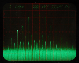
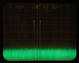
Below are displays from the Tek with tones spaced 20 kHz, and LP-PAN with tones spaced 1200 Hz. You can see where the resolution bandwidth of LP-PAN/PowerSDR is quite welcome. The same would hold true for other decoding applications like SpectrumLab or SpectraVue. The panadapter display could actually be zoomed in much more if needed These pictures were not taken under the same conditions of drive level, so cannot be compared directly, but you can see the similarities. Looking at 20 kHz spaced tones on LP-PAN results in traces that are thin vertical lines because of the enhanced resolution bandwidth.
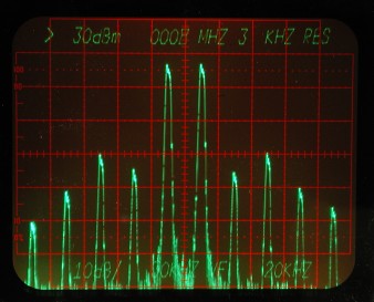
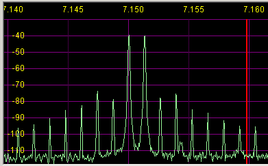
If the transmitter output is attenuated to about -20dBm, the distortion of the K3 and LP-PAN can essentially be ignored, as it will be below the noise floor. This guarantees that the testing hardware will not color the results. It still leaves at least 80dB of measuring range, which is comparable to a professional spectrum analyzer.
Note: All test results were obtained using an E-MU 0202 USB sound card. Similar results can also be obtained with the M-Audio Firewire Audiophile card (96 kHz sampling) and E-MU 1212m PCI sound card (192 kHz sampling).
Email me for more info.
73,
Larry N8LP
LP-PAN is a software defined IQ direct conversion receiver with integrated SDR application to provide a high quality panadapter to rigs with IF output jacks. The unit uses a combination of SMT and through-hole technology, a custom aluminum case with powder coated finish and silk-screening. Pricing for an assembled and tested unit is $225 plus shipping, and a kit is available for $175 with SMT parts pre-installed. The kit takes an average builder about 2 hours to complete, plus another few minutes to adjust the front end filter. LP-PAN is aimed at the Elecraft K3, but can also be used with many earlier Kenwoods with IF output jacks, Yaesu FT950/2000/5000, as well as TenTec Orion and Elecraft K2 when modified to bring out the IF signal.
Here is a list of current features...
* Crystal controlled local oscillator for low phase noise.
* Up to 192 kHz display on PC, sound card dependent
* Switching quadrature detector for high dynamic range
* Strong buffer amp with very high LO isolation to protect K3.
* Ground isolated inputs / outputs with mil spec audio output xfmrs
* Fully balanced architecture with balanced and unbalanced outputs
* Jumperable ground lift on RF input and audio outputs
* Point and click frequency control with PowerSDR / IF Stage. In addition, LP-Bridge allows sharing of K3/LP-PAN with up to five loggers, PSK programs, CW-Skimmer, etc.
* Usable with many other SDR programs for basic panadapter display.
* Powder coated aluminum enclosure with silk screened graphics.
* Hardware or software mute
* Available for the following IF frequencies...
8.215 MHz (Elecraft K3)
8.83 MHz (most older Kenwoods)
9.00 MHz (Yaesu FTdx5000, TenTec Orion)
4.915 MHz (Elecraft K2)
10.7 MHz (IC-R8500/9500 and others)
10.55 MHz (FT-950/2000)
Orion & K2 require hardware modification to add an IF output port. IC-R8500/9500 require the addition of a blocking cap in the RF cable to LP-PAN. FT-950/2000 require IF-2000 interface board (see link above).
Here are current specifications (sound card dependent). Note: Measurements represent the composite results of K3 / LP-PAN. Standalone LP-PAN performance is even better.
* Approx. -125dBm MDS with K3 preamp on (about 8dB better with K3 buffer mod installed).
* +2dBm maximum input with K3 attenuator on
* ~105 to 115dBm dynamic range, depending on sound card
* 80-90dB image rejection with PowerSDR-IF
* Greater than +20dBm IP3 @ -15dBm, 2kHz to 20kHz spacing (composite value for K3/LP-PAN combo)
* ~90dB IMD DR @ -35dBm, 2kHz to 20kHz spacing (composite value for K3/LP-PAN combo)
* THD ~ 0.005%
* 600 ohm output Z, balanced or unbalanced.
* +2dBV (1.27 Vrms, 3.6V p-p) nominal output level at recommended maximum RF input
* Adjustable gain to interface almost any sound card
* L.O. offset to allow use with older sound cards
* 11-16 VDC @ 55 mA
Note: Specifications dependent on sound card, and subject to change. Cited values were taken with an E-MU 0202 USB sound card. All measurements also apply to M-Audio Audiophile 2496 PCI or FW cards (limited only by 96 kHz display width), the Infrasonic Quartet and E-MU 1212m PCI sound card. Measurement details are included in the Performance section below. PowerSDRTM is an open source application for use with IQ based software defined radios, and is a trademark of FlexRadio Systems.
Hardware:
LP-PAN consists of a multipole bandpass filter, followed by a strong buffer amplifier with high isolation, followed by a balanced switching mixer. The output of the mixer is fed to two pairs of balanced low noise op-amps with ultra wideband 600 ohm output transformers for flexibility in sound card interfacing. I have also tried to maximize interfacing flexibility with the sound card, to minimize hum and noise issues there. The devil is in the details, and that is where I have concentrated my efforts to make LP-PAN the best integrated panadapter solution for use with K3.
Software:
LP-PAN can be used with most SDR decoding applications, like PowerSDRTM, Rocky, SpectraVue, Spectrum Lab, TRX-Pan, etc. With NaP3, TRX-Pan or the /IF branch of PowerSDRTM and LP-Bridge, point and click frequency tuning is available. LP-PAN will also work with other programs which will decode an audio IQ signal, like the nifty CW Skimmer from Alex, VE3NEA. The pictures in the performance section below are taken from various flavors of PowerSDRTM.

LP-PAN allows you to use your PC / sound card as a second receiver with lots of nice features if you use the PowerSDRTM app. Shown above is split operation using the main and sub receivers in PowerSDR. VFO A (green) from the K3 is linked to the main receiver in PowerSDR, and VFO B (blue) is linked to the sub receiver. The K3 doesn't need the KRX3 2nd receiver option. PowerSDR provides both receivers. PowerSDRTM has lots of flexibility in terms of modes, bandwidths, interference reduction tools, etc. I find listening to SW broadcasts with the synchronous AM detector very nice.
Here
is version 0.9.9.76
of LP-Bridge program (reduced size image). It does several
things...
1) It provides a method of allowing several applications to simultaneously share bidirectional communications with the K3 by creating up to 5 virtual ports for the other applications to connect to. Communications are optimized to eliminate collisions and minimize traffic to the K3.
2) It provides a means to obtain offset data from the K3, and passes it along to WU2X's IF Stage version of PowerSDR to keep the two IFs synced.
3) It provides a convenient way to implement point-and-click tuning from PowerSDR /IF Stage by providing an extensive interface to PowerSDR.
4) It provides frequency linking to hardware such as SteppIR antennas, AT-Auto tuner and amplifiers.
Setup allows you to add an application name to go with each virtual com port to keep things straight. The ports can all be automatically created/connected when LP-Bridge launches, and the associated applications can automatically be launched as well, including up t two instances of PowerSDR-IF (for SO2R). Typical choices for applications would be loggers, a PSK application or something like CW Skimmer... any application that requires serial communication with the K3. To maximize throughput, all normal polling is handled by LP-Bridge. Polling requests from the applications are responded to directly by LP-Bridge, from a "virtual K3" mirror, preventing collisions from multiple requests to the K3 from various programs. Handskaking lines for CW and PTT keying are passed through to the K3 to allow PTT or CW keying using DTR or RTS.
For more details or to download the program, go to the LP-Bridge page.
Performance:
Note: All test results were obtained using an E-MU 0202 USB sound card. Similar results can also be obtained with the E-MU 1212m or 1616m PCI cards, or the Infrasonic Quartet PCI card. At up to 96 kHz, the M-Audio Firewire Audiophile card (discontinued but available on eBay) or E-MU 2496 PCI card will also produce similar results. Except for the 1616m, these cards are all priced in the $80-150 range.
Performance is a composite of LP-PAN / K3 system unless otherwise noted.
Usable Dynamic Range:
When connected to the K3, LP-PAN provides up to 115dB dynamic range between noise floor and clipping, depending on sound card. Below is an example of LP-PAN working with PowerSDRTM. There is no higher order distortion visible at a level of -20dBm (~ S9 + 53dB) from my HP-8640B signal generator at this bandwidth setting. 2nd harmonic, not shown, is about 80dB down. Increasing the level to -10 dBm (~ S9 + 63dB), about 5 dB before clipping, a couple small distortion products appear about 10-15 dB above the noise floor. The average noise floor is about -120 dBm (~0.2uV for 10dB S/N) in this setup. This test was run with the K3 preamp OFF. Noise floor with the preamp ON is about 10dB better. The smaller blip is the image, which is 70dB down (Image Rejection with PowerSDR-IF v1.19.34 has improved to >80dB).
In
addition, there is a little mod
that I have developed for the K3 which improves the noise floor by
about 6dB. It requires changing two SMT resistors with either SMT or
standard 1/8W resistors to reduce the loss in the K3 buffer. Details of
the buffer mod can be found here, K3
Buffer Mod . Elecraft now
ships K3 with a similar mod, and provides a mod kit for older K3s.
The above display shows typical image rejection with older version of PowerSDR-IF. The latest version, v1.19.35, uses the new Wide Band Image rejection (WBIR) feature of PowerSDR, and provides image rejection of 80-90dB or better over the entire display, with no user adjustment. WBIR "learns" the correct values and saves the parameters in a database file. This means that a signal of S9 + 30dB to S9 + 40dB will have no visible images. More information regarding image rejection can be found on the SOundcards web page, http://www.telepostinc.com/soundcards.html
Spurs:
There are many reasons why a user might see spurious signals in his display.
Many of them, if not most of them, are stray signals from local noise sources around the home and neighborhood. Some come from the shack in the form of noise from a PC, serial or USB cables, switching power supplies, etc. These signals can be picked up in the cabling between LP-PAN and the rig, power supply or sound card. In general, if the spurs don't change with band changes, they would fall into the category of locally generated noise entering through connecting cables. Careful grounding, selection of well filtered power supplies and use of high quality shielded cables should eliminate these.
Some spurs may actually be radio signals that are unidentifiable. These would change with bands and band conditions.
And some can be generated in the rig itself in the form of images generated in the rig's front end and spurs generated by the rig's synthesizer. Since LP-PAN is generally fed by a buffered output of the rig's 1st mixer, any strong image signal getting through the rig's front end filter can cause a spur. Also, unwanted signals from the synthesizer chain can mix with desired or image signals, or just be passed through to the mixer output. Note that you may see spurs from on the rig's IF output port that you can't hear on the rigs audio output. Since synthesizer spurs can be calulcated, manufacturers can use digital wizardry to blank out the spurs in the DSP processor which is downstream of the IF output.
The RBW (Resolution Band Width) setting in the SDR application can also affect what you see. RBW is defined as the smallest frequency interval that the software can display, and is determined by the total bandwidth of the display and the number of samples (or FFT bins) that are used across the display. In PowerSDR/IF the RBW is a fixed value dependent only on the sound card sampling rate. The number of bins is 4K (4,096), and the sampling rate is usually 192kHz, but can also be set to 48kHz or 96kHz. At 192 kHz sampling rate, each bin represents a frequency change of ~48Hz. Many spurs can fall between steps this large. In NaP3, the user can select up to 64K FFT samples. Frequency changes are thus 16X smaller, or 3Hz. Clearly, it would be harder for a spur to hide with this kind of resolution. The question is, how much RBW is enough. Most users should find that 16K FFT samples would be more than enough except possibly at the narrowest of displays spans (below 10kHz). Below are pictures of the 6m band at N8LP with a span of 80kHz and various conditions as captioned.

Above:
K3, no antenna, FFT setting of 4K. Note the absence of spurs.


Above:
K3, no antenna, FFT setting of 64K. Note many more spurs visible
because of the finer RBW and lower noise floor due to oversampling.


Above:
LP-PAN cable unplugged from K3 IF output jack. Note noticeable
reduction of spurs without any change in noise floor.
Blocking Dynamic range (BDR):
I wanted to make sure that the K3 was the limiting factor when used with LP-PAN, at least up to the maximum signal level of LP-PAN, which is +2dBm (S9+75dB). To test the BDR performance of the LP-PAN / PowerSDRTM combo, I set up the following test...
I fed a strong signal (S9+50dB) to the K3 using a homebrew xtal oscillator which has very low phase noise. 2kHz away I mixed in a 3uV signal from my HP-8640B signal generator using a hybrid combiner. The widening of the base of the signal from the xtal oscillator is due to the phase noise of the K3. I purposely used a xtal local oscillator for LP-PAN to minimize phase noise degradation. The 3uV signal in this case has about 10dB SNR, more than enough for solid copy. In practice, this situation would never occur since most transmitters are far noisier than my xtal generator, and the transmitter noise would bury any weak signal 2 kHz away. Receiver design has clearly advanced to the point where it far exceeds transmitter design.
IMD Dynamic Range:
Here is a comparison of IMD DR with the standalone LP-PAN, and through the K3. The setup is the same as the one for the BDR test above, except that both the xtal oscillator and the HP-8640B are set to the same level. Signal levels are -33dBm (S9 + 40dB), and signal spacing is an amazing 500Hz! The slightly wider signal on the left is the HP, but it's still excellent phase noise performance compared to today's synthesized generators, and stands up well against the xtal oscillator. As you can see in the top picture for the standalone LP-PAN, IMD DR is >90dB, with no extraneous distortion products. Quite amazing for this bandwidth.
The bottom picture was taken with the K3 in line, with the K3 preamp Off. You can readily see the effect of the K3 phase noise by comparison. Reciprocal mixing with the K3 synthesizer noise sidebands produces a noise hump around the signals. This is actually excellent performance for a synthesizer, but clearly degrades close-in dynamic range. We have also picked up some minor blips.

L.O. leakage / isolation:
Because LP-PAN connects to an unprotected IF port on the radio, it is important that any LO leakage in the rig's passband be very low. This is something I spent a lot of time on in design and testing. As a result, the measured LO signal at the input of LP-PAN is -135dBm (~0.05uV). Adding in an estimated 20dB+ isolation for the buffer in the K3, this should be a more than adequate amount of isolation to prevent any issues with the K3. In my initial testing, I have not been able to detect LP-PAN's LO in my K3, confirming that the leakage is below the noise floor of the K3. For comparison, the LO leakage of a couple SoftRock receivers that Jack, K8ZOA and I checked, measured about -40dBm (S9+33dB)... almost 100dB higher than the buffered LP-PAN.
I also added more filtering to the input of LP-PAN to filter out the numerous spurious signals I found in the K3 IF output. These signals include LO leakage from the K3, plus harmonics and mixing products of them. The picture on the left shows the K3 IF output with one signal in the passband over an 80 MHz span. The second picture shows the same conditions with my filter installed. In practice, I see a number of products sliding through the panadapter display as I tune without the filter, but none with it.


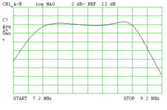
An
added benefit is that the filter also multiplies with the K3 bandpass
filters to provide more protection against out-of-band interference.
Here is a composite measurement of the cascaded filters on 20m...
To minimize installation problems, I added transformer coupling of the IF port and mil spec audio xfmrs, all with "ground lift" jumpers to minimize hum and noise in the audio interface. Audio output is 600 ohms to allow driving any sound card, and one channel has an adjustable load to balance out any termination variations in the sound card / cabling. This level of detail is required to acheive the image rejection that we are able to get, which rivals a superhet with xtal filtering when carefully adjusted. The outputs can also be used in either balanced or unbalanced mode for further isolation when a professional sound card with balanced inputs is available. As the PowerSDR screen shots show, there are no spurious hum or noise signals from the audio interface in my installation... even at the 0 Hz center frequency.
Using LP-PAN as a spectrum analyzer:
One of the more useful pieces of test equipment for ham use, but also one of the more expensive, is a spectrum analyzer. An example of a good use of LP-PAN in this regard is a project I worked on. I was asked by the FDIM organizers to build and test their 2008 Dayton Buildathon project, a 10W QRP amplifier for CW/SSB. I have a Tektronix 7L13 spectrum analyzer, and normally use this for testing spurious emissions like harmonic suppression and IMD. The Tek works great for checking harmonics, and IMD with fairly wide tone spacing, but is not so good at displaying IMD with 1200 Hz tone spacing as is commonly used to check SSB amplifiers.
Below are displays from the Tek with tones spaced 20 kHz, and LP-PAN with tones spaced 1200 Hz. You can see where the resolution bandwidth of LP-PAN/PowerSDR is quite welcome. The same would hold true for other decoding applications like SpectrumLab or SpectraVue. The panadapter display could actually be zoomed in much more if needed These pictures were not taken under the same conditions of drive level, so cannot be compared directly, but you can see the similarities. Looking at 20 kHz spaced tones on LP-PAN results in traces that are thin vertical lines because of the enhanced resolution bandwidth.
If the transmitter output is attenuated to about -20dBm, the distortion of the K3 and LP-PAN can essentially be ignored, as it will be below the noise floor. This guarantees that the testing hardware will not color the results. It still leaves at least 80dB of measuring range, which is comparable to a professional spectrum analyzer.
Note: All test results were obtained using an E-MU 0202 USB sound card. Similar results can also be obtained with the M-Audio Firewire Audiophile card (96 kHz sampling) and E-MU 1212m PCI sound card (192 kHz sampling).
Email me for more info.
73,
Larry N8LP