Basic Interconnect Diagram
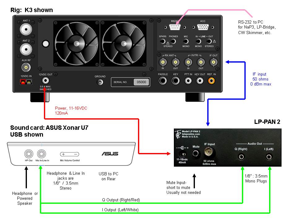
The sound card shown is the Asus Xonar U7, but the U5 is similar and a little cheaper. The only difference in terms of hardware is that the input and output jacks are on the back of the U5. They are labeled with a microphone icon for input and a headphones icon for output. The control panel selects whether the input will be mic or line level, and whether the output will appear as headphones or speakers.
FTdx3000/5000... IF - 50 ohm jumper with male BNC to male RCA connectors.
Audio
– Y cable with 1/8” (3.5mm) stereo connector on one end and 8”
mono connectors
on the other end. These can be homemade, premade or made up of a
combination of
premade cables and adapters. A common configuration is Y cable with
stereo 1/8" (3.5mm) on one end, and red/white RCA connectors on the
other end. Adapters are used to convert the RCAs to 1/8" (3.55mm)
mono. NOTE: L / R cables need to be swapped for
FT950/2000, or the "Swap I/Q" checkbox on the input tab in NaP3 needs
to be checked (the IF-2000 boards flips the sidebands).
RS-232C... Connect to a serial port on your PC, or to a USB to serial adapter. We recommend adapters which use FTDI chipsets. We recommend against adapters which use Prolific chipsets.
Headphones/Powered
Speaker – Requires 1/8” (3.5mm) stereo plug. It is smart to use
speakers with a
volume control, even though the U7 has its own volume control, and NaP3
has volume sliders. Headphones can be anywhere from 8 to 64 ohms. The
U7 control panel allows you to select a matching impedance. The main
rcvr in NaP3 feeds the left channel and the sub rcvr feeds the right
channel.
Return
to LP-PAN 2
Installation 1-2-3
Continue
to ASUS Xonar U7
Installation