LP-500 / LP-700 Digital Station Monitor
Digital Power /SWR Meter, Waveform Monitor Scope and Modulation Spectrum Display all in one convenient package.
Above picture shows the relative sizes of the LP-500 and LP-700 in comparison with other familiar pieces of equipment at N8LP.
What is LP-500?
LP-500 is a digital station monitor which displays detailed information about the transmitted signal of a station. It displays the sampled signals in numerous formats including Power/SWR, various oscilloscope type displays and a spectrum display. The sampled signals are obtained by demodulating the RF, like in a traditional wattmeter, and should therefore work on any frequency for which there is a suitable directional coupler with the appropriate voltage scaling and time constants. It should be noted that demodulated samples are audio frequency based and not the same as RF samples. With some types of modulation, the demodulated audio is not a linear representation of the modulation signals, therefore the spectrum display works quite differently than a true spectrum analyzer. This doesn't pose a problem for AM signals, where the demodulated audio is faithful to the modulation signal, but is a challenge for SSB and other signals without a carrier. For this reason, we have developed special test signals which allow for some traditional SSB tests to be performed, although the tests cannot be directly compared to measurements from a true spectrum analyzer. In many cases, though, similar information can be gleaned from the tests, and they can be used for comparative tests to see the effect of changes to the transmitting equipment.
ORDERING
The following buttons are used to build a DOMESTIC U.S. order for LP-500 or LP-700 (for international orders, please email Larry to receive a quote and PayPal invoice). For those who prefer not to use PayPal, you can phone us at 734-455-3716. Note: All credit card orders are processed through PayPal's merchant card services. To avoid PayPal altogether, orders can be placed via mail with a check or postal money order, or via direct bank wire transfer. Email or call us for details.
Step 1 - Start with the meter selection, LP-500 or LP-700. Click "Continue Shopping" in PayPal Cart to return to this page for further additions.
Step 2 - Add desired couplers up to a total of four couplers. Quantities can be adjusted in PayPal Cart if needed.
Step 3: Proceed from PayPal Cart to Checkout, where you will be able to select a shipping speed. NOTE: You can click "View Cart" button at any time to make any final adjustments to quantities or selections, or to place the order.
Step 4: Don't forget to include a phone number with your order. Most shipping companies prefer a phone number for shipping in case of delivery problems.
Upon completion, you will receive an email confirmation of your order from PayPal.
| LP-500 (does not include any couplers). Please add couplers below..... $725 | |
| LP-700
(does not include any couplers). Please add couplers below..... $800 |
|
| LPC501,
HF/6m 3KW PEP Coupler with SO-239 Connectors... $150 |
|
| LPC501N,
HF/6m 3KW PEP Coupler with N Connectors... $200 |
|
| LPC502,
HF/6m 5KW PEP Coupler with SO-239 Connectors... $225 |
|
| LPC502N,
HF/6m 5KW PEP Coupler with N Connectors... $275 |
|
| LPC503,
HF 10KW PEP Coupler with SO-239 Connectors... $225 |
|
| LPC503N,
HF 10KW PEP Coupler with N Connectors... $275 |
|
| LPC504U,
2M 3KW PEP Coupler with SO-239 Connectors... $200 |
|
| LPC504N,
2M 3KW PEP Coupler with N Connectors... $250 |
|
| 12VDC / 1A
Wall Mounted Power Supply w/Linear Regulator... $15 |
Click button below to view your cart and/or complete your order:
Please allow up to a week to process and ship your order.
_______________________________________________________________________________________________________
Click here for LP-500/700 User Guide in English.
Click here for the LP-500/700 User Guide in German. Translation provided by our dealer in Germany, Difona Communication (www.difona.de)
Click here to join the LP-500/700 User Group.
 March 2018
QST Product Review
of the LP-500
March 2018
QST Product Review
of the LP-500Reprinted with permission of ARRL.
 Visit
eHam.net Product
Review page for LP-500/700
Visit
eHam.net Product
Review page for LP-500/700Click here for a gallery of LP-500/700 installation pictures.
Click here for Encoder Mod for very early units.
Free plug in daughtercard for early LP-500 / 700 to improve optical encoder response. Affects LP-500 with serial number below 00030, or LP-700 with serial number below 00018. Models later than these come with the mod installed, or on newer boards integrated into the main PCB. Email Larry if you would like one of these.
* The list is used to determine seniority for regular retail sales of new production units. Excludes beta units, demo units, units used for development / testing and a small allotment of dealer orders.
Downloads
Firmware and software are posted in the downloads section of this page, along with firmware history, for those wishing to flash update their firmware. This is a fast and easy process once you have learned it. Instructions are in the User Guide on page 11. You can download the Bootloader program and the firmware by clicking here.
Note: Users should report any bugs in beta programs to N8LP.
73,
Larry N8LP
_________________________________________________
Watch LP-500 / LP-700 Video...
First video of LP-700, sitting side by side with the LP-500 and the LP-100A for size comparison. Due to the limitations of the HD camera, this is not a good comparison of the resolution of the displays, which is actually the same, but still a good comparison of size. This video shows the latest firmware and provides examples of some common operating and testing scenarios.
Note: The video starts in Standard Definition, but if you click on the far right icon in the toolbar at the bottom of the video window, it will zoom to full screen High Definition. With a broadband connection, the video should be smooth and glitch free, even in HD.
_________________________________________________
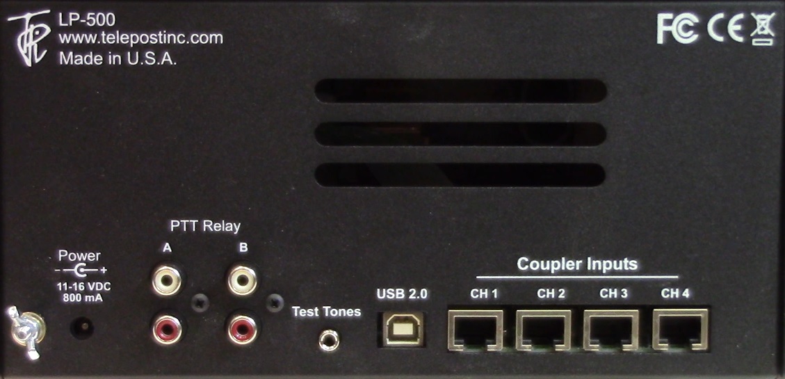
General Features * Bright 5" Color TFT Display w/ 800 x 480 Resolution * LP-700 has a larger enclosure and a 7" Display, otherwise the two meters are the same. * 32-bit Main Processor * Touchscreen controls of all functions, plus physical switches for the six main function keys * Graphics and Audio coprocessors * (8) 16-bit / 200 ksps ADCs with Adjustable Oversampling * Low Distortion Proprietary Custom Digital Test Signals to Aid in Rig & Amplifier Adjustments using WFM and Spectrum Displays. * Distinctive Aural/Visual Alarms for Each Channel for both Power and SWR. * Native USB Interface - No Drivers Needed (not needed for normal operation) * Flash Upgradeable * Includes Windows based "VM" (Virtual Meter) software which allows computer control and monitoring of the LP-500 locally, or remotely using RDP or a USB Device Server. * Fast Screen Refresh * 12VDC Operation / 800 mA maximum. * Interface to Rig is Through Remotable RF Couplers using CAT5/6 cable of any practical length. * Provides Extensive Information About the Quality of Your Transmissions * Size: LP-500: 9.125"W x 6.1"D x 4.88"H (23.2cm x 15.5cm x 12.4cm) LP-700: 10.125"W x 6.1"D x 5.63"H (25.7cm x 15.5cm x 14.3cm) Watt / SWR Meter Features * Couplers for HF, VHF, UHF... Power up to 10KW (VHF / UHF available soon) * Up to 4 Couplers with Simultaneous Sampling & Auto-Ranging * NIST Traceable Calibration * Large Numerals for Power and SWR at a Glance * Simultaneous Bargraphs for Instantaneous Peak Pwr, Average Pwr & SWR * "Sticky" bar displays highest peaks in all modes * Flexible Multi-Channel SWR & Power Alarms w/ Adjustable Set Points * SWR Protection Relay Jacks for 2 Amplifiers *Optical Encoder Adjusts Averaging Time (Fast, Medium, Slow) Waveform Monitor Scope Features * Full screen Waveform, Trapezoid & Scope Displays (Trapezoid requires two couplers) * Adjustable Sweep and Trigger with Memory. * 5 Presets for SSB, CW, PSK plus 3 User Selections * 10 Vertical Scales per Channel with Memory * Multiple "Split-Screen" Displays with Combinations of Waveform, Power/SWR, Trapezoid and AM Modulation (w/ Bargraphs/Readouts for Positive & Negative Peaks). * Touch Screen Cursors for Measuring Time Intervals & Levels * Adjustable Peak Markers to Show Preset Power Limits * Freeze Button to Facilitate Touch Screen Measurements *Optical Encoder for Adjusting User Sweep Presets and Trapezoid Horizontal Gain (Width). Spectrum Display Features * Displays Modulation Spectrum of Transmitted Signal, as sampled by the coupler * * Adjustable Span & Averaging * Linear and Log Frequency Scales * Adjustable Vertical Reference with +75, +65, +55 & +45 dBm Full Scale * 18 bits Effective Resolution * Up to 80 dB Measurement Range * Touch Screen Cursors for Measuring Frequencies & Levels * Adjustable Peak Level Marker * The Spectrum display does not sample RF directly, so results cannot be compared directly to an RF spectrum analyzer. Useful comparative measurements can be made, however. Because the couplers employ diode envelope detectors, signals without a carrier would normally be distorted during demodulation. To account for this, we provide special test signals for these modes which add subcarriers to simulate the existence of a carrier. See usage guidelines in the User Guide for more details. While the LP-100A couplers look similar to the LP-500 couplers, they are completely different and are therefore not compatible. Important notice for LP-100A owners: LP-500 will not replace the LP-100A. The LP-100A will continue with some important features not provided in the LP-500. Preliminary Specifications… (with LPC-501 coupler) Subject to change without notice. General Power Range… 0.1W to 3KW PEP / 1500W Average Absolute Power Accuracy… Better than 5% at 14 MHz, NIST traceable. (Reduced accuracy below 5W) Flatness… Better than +/- 3% from 1.8 to 54 MHz (+/- 1% dB typical from 1.8 to 30 MHz) Directivity... >30 dB, 1.8 to 54 MHz Return Loss... >40 dB, 1.8 to 54 MHz SWR Range… 1.00 to 9.99 SWR Accuracy… 5% Bar Graph Resolution... 600 steps for each range, Manual or Auto-Ranging Number of Channels… 8 simultaneous (FWD & REF power for 4 couplers) Channel Balance... +/- 0.1% Memories... Range & Alarm settings are saved per channel Channel settings are saved per mode A/D Converter 16-bit / 200ksps, plus oversampling (2X to 16X). DAC Resolution… 18-bit, 96 dB SNR Screen Refresh… 5 Hz to 70 Hz, depending on mode, sweep/span settings. Sampling Rate… 2.5k to 80 ksps, depending on mode, sweep/span settings. Display Resolution 800 x 480 pixels (WVGA) Display Type TFT with White LED Backlight Display Size LP-500: 5" Diagonal, LP700: 7" Diagonal Test Tone Output… 250 ohms, 350-500mVpp, unbalanced, 0.01% THD into 10K load Power Requirements… 12-16VDC @ 800 mA maximum Size… LP-500: 9.125"W x 6.1"D x 4.88"H (23.2cm x 15.5cm x 12.4cm) LP-700: 10.125"W x 6.1"D x 5.63"H (25.7cm x 15.5cm x 14.3cm) Scope Sweep Rate … 1.0 to 20.0 ms/division in 0.1 ms steps 5 Factory Presets and 3 User Adjustable Presets Display Modes … 7, including 4 split screens Trigger Modes … Normal, Plus, Minus, Plus/Minus, Free Running. AM Modulation % … 0 to 150, positive. 0 to 100 negative. Cursors … 2, measuring peak voltage and time (ms) Markers... 1 or 2, adjustable to show preset power limits Spectrum Frequency Spans... 2.5, 5.0 & 10.0 kHz, w/linear or log scaling Span Multiplier... 5X (500 & 1000 Hz, linear) RBW… 1 to 20 Hz, depending on span Averaging… 2X to 16X Full Scale Reference… +45, +55, +65 dBm ADC Dynamic Range… > 90 dB Coupler Dynamic Range... Up to 80 dB, depending on modulation type Cursors … 2, measuring peak power (dBm) and frequency (Hz) Markers... 1, adjustable to show preset power limit Additional Couplers LPC-502 Range... 5KW PEP / 2500W average Flatness... Better than +/- 3% from 1.8 to 54 MHz (+/- 1% typical from 1.8 to 30 MHz) Directivity... >30 dB for 1.8 to 54 MHz Return Loss... >40 dB from 1.8 to 54 MHz LPC-503 Range... 10KW PEP / 5KW Average Flatness... Better than +/- 5% from 1.8 to 30 MHz (+/- 3% typical from 1.8 to 30 MHz) Directivity... >30dB from 1.8 to 30 MHz Return Loss... >40dB from 1.8 to 30 MHz Additional Couplers will be available for VHF/UHF, lower power HF, etc. Connections: Power:
12-16
VDC @ 800 mA maximum, center pin positive, 5.5mm OD / 2.5mm ID. The
supplied
Creating your own test tones... In
addition to the built in tones, you can create your own tones and save |
   Main Power/SWR screen showing
Peak Hold power value. Also shown in the bargraphs and small numbers
are continuously updating peak and average power.
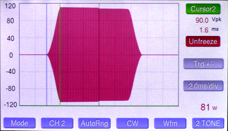 Waveform screen showing keying
envelope with + / - edge triggering at 30 wpm. This allows display of
both edges of the envelope at the same time. You can also see a slight
drop in power putput over the duration of the keying element in this
case. Also displayed are adjustable cursors,
which in this case show risetime of the cw envelope (1.6 ms). The
cursors work in all WFM modes and measure various parameters. The
freeze
button makes measurements easier.
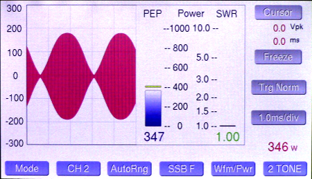
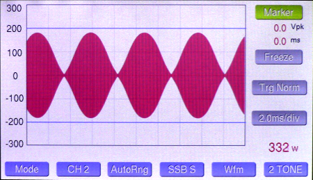 Two-tone SSB waveform using
built in two-tone generator. Also shown are the peak power markers,
currently set to 400W.
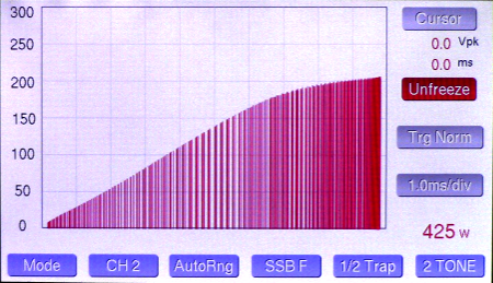 1/2 Trapezoid display showing
amplifier overloading using built in two-tone generator. This view
gives twice the resolution of a the standard trapezoid display.
 Waveform | Trapezoid split-screen  AM Modulation screen.
 Waveform | Power/SWR split screen.  Trapezoid | Power/SWR split screen. New in firmware v2.49  Two-tone IMD test
 Frequency spectrum of
transmitted audio with white noise signal
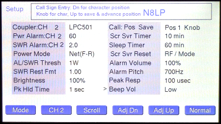 Setup screen. The first three
entries can be set differently for each of the four channels.
|
|
Connecting Test Tone Output to Your Rig… The Test Tone output is
intended to feed a line level audio input of the rig. Some rigs have a
dedicated jack for this, but some of the newer rigs which have limited
space
for connectors don’t. Most rigs have a DATA connector, which is meant
to be
connected to a TNC or Sound Card RTTY interface. These usually take the
form of
a DIN or mini-DUN connector. Sometimes these are labeled ACC-1, ACC-2
or ACC-3.
The pins that you want to look for are usually labeled Data IN
and Gnd. These would connect
to the tip and sleeve of the audio jack on the LP-500. An alternative is to use the front panel MIC jack on the rig, either an 8-pin round or 8-pin modular (Ethernet type) connector. You will need an interface like the inexpensive W2IHY iBox to make this connection. The iBox accepts the unbalanced line level output of the meter, and converts it to any number of outputs to feed various connectors on your rig, either front panel or rear panel. Julius, W2IHY can direct you to the best option for your rig. It is generally preferred to use a rear panel connector so that the microphone (or mixer) can remain plugged into the front panel. This will usually allow you to have independent gain controls for the mic and meter levels, so that they can be matched. If the levels aren’t matched, adjustments made with the test tones will not correlate directly to microphone use. Here is Julius' information...
Website:
www.w2ihy.com W2IHY
Technologies Inc. Toll
Free: 877-739-2449 |
For the latest downloads, visit:
LP-500/700 Downloads (Version 2.51.30b2 and later are not compatible with VM versions older than version 1.076. Some of the new functionality regarding trapezoid display is not fully functional on VM yet).
Note: Users should report any bugs in beta programs to larry.
LP-500/700 Major Firmware Version History: Note: Legacy versions can be downloaded from http://www.telepostinc.com/Files/LP-500/
| Version |
Release
Date |
Notes |
|
| 2.51.30b2 |
8-10-18 |
* Fixes bug on some meters with erratic behavior of CH1/2 trapezoid display. | |
| 2.51.30b |
4-2-18 |
Includes: * Support for LPC-504 legal limit VHF (2 meter) coupler. * Fix for incorrect reflected power behavior in Peak Hld mode. * Improved trap display. * Change to USB routine to allow better access to power and SWR data for 3rd party developers. |
|
| 2.51.09b |
1-30-18 |
* Fixes
firmware coding error that caused power to read about 5% high at power
levels of 500W or more. |
|
| 2.51.08b |
11-26-17 |
|
|
| 2.51.06b |
11-23-17 |
*
Corrects reflected power calculation bug at high power * Minor cosmetic changes |
|
| 2.51.05b |
11-11-17 |
*
Improves averaging calculations at low power. * Removes the yellow sticky bar in the Tune mode. |
|
| 2.51.03b |
11-3-17 |
* Fixes a couple bugs in the last beta. * Changes the auto ranging so that it doesn't return to the base range until the end of a transmission. *
Adds a reflected power readout (in watts) to the SWR window.
|
|
| 2.50.23b |
10-24-17 |
Replaced
due to bug. * Fixes a bug in previous beta where the peak hold value occasionally didn't reset. * Changes the behavior of the peak bargraph * Changes "sticky" bar to yellow for better visibility * Improvements in the power averaging algorithm and bargraph display * Addition of Slow/Med/Fast settings for averaging, using knob for selection. * Improvements to the Wfm/Pwr and Trap/Pwr split screen power/SWR bargraphs |
|
| 2.50b6 |
10-9-17 |
Replaced
due to bug. * Fixes bugs in previous beta * Adds knob select button to Wfm screens to allow the user to select whether the adjust knob controls sweep or trap width (amp gain). * Changes power bargraphs in Wfm split screens to mimic the Pk Hold / Avg / Tune settings from the main screen. * Adds a couple error messages and an error beep sound to indicate improper button presses. |
|
| 2.50b |
9-29-17 |
Fixes bug from two previous releases. Changes trapezoid width (amplifier gain) adjustment from touch screen to knob control, and includes smaller steps of adjustment. Changes power display to 1W steps above 100W to minimize flicker in the last digit. | |
| 2.49 |
9-23-17 |
Adds
Trap | Power/SWR split screen. |
|
| 2.45 |
8-13-17 |
Improves
accuracy of the meter at very low power levels. |
|
| 2.43 |
7-08-17 |
Improves
behavior of AM Mod bargraphs. |
|
| 2.42 |
4-28-17 |
Adds support
for VM v1.073 |
|
| 2.41 |
4-18-17 |
Adds
enhanced support for LPC-502 and LPC-503 couplers in Wfm mode. |
|
| 2.38 |
3-26-17 |
Adds volume
settings in Setup for confirmation beeps. Options include Off, Low,
Med, High. Made improvements to the alarm system. |
|
| 2.36 |
3-20-17 |
Fixes Avg
Pwr display in WFM modes, fixes SWR problem with VM. |
|
| 2.35 |
3-05-17 |
Fixes alarm
reset bug. |
|
| 2.34 |
2-26-17 |
Change alarm
indicators to make them more visible. See comments near the top of this
page. |
|
| 2.33 |
2-21-17 |
Adds Tune
mode (like LP-100A) and supports the latest VM software release. |
|
| 2.31 |
1-30-17 |
Fixes bug in
v2.30 which caused the small blue peak number to the right of the peak
bargraph to display the wrong value for time varying signals. |
|
| 2.30 |
1-13-17 |
Added
wattmeter "Peak Response" oversampling adjustment to SETUP. Choices are
50, 100, 200, 500 usec. This allows the user to decide how short of
spikes he wants to allow the meter to capture. |
|
| 2.29 |
10-23-16 |
Fixed bug
with the 60 minute sleep timer choice. |
|
| 2.28 |
10-21-16 |
Fixed bug
associated with SWR Resting choice of "LAST" (wasn't displaying
properly in WFM/PWR split screen). |
|
| 2.27 |
10-20-16 |
Added more
timeout options to screensaver and sleep timers, including a sleep
option of "Never Sleep". |
|
| 2.26 |
10-10-16 |
Bug fixes -
WFM Range button recall value in 1/2 Trap display. CH2 Sweep recall
value. |
|
| 2.25 |
9-23-16 |
Expanded
amplifier gain options to include 10dB & 11dB for amps with lower
gain |
|
| 2.24 |
9-16-16 |
Added
3W choice to AL Threshold Options and changed SWR numeric display
averaging window. These changes produce more stable SWR indication
while talking. |
|
| 2.23 |
9-06-16 |
Changed
SWR Rest Fmt to eliminate a choice and fix the "LAST" choice. |
|
| 2.22 |
8-23-16 |
Fixed bug in
v2.21 which didn't properly recall previous amplifier gain setting. |
|
| 2.21 |
8-21-16 |
Adds
a gain selector to the trapezoid modes to allow the user to tailor the
trap width to match the gain of his amplifier. It was determined that
this was needed to accommodate the latest tetrode and LDMOS amplifiers
which have considerably more gain than the FCC rules have previously
allowed. The range is 12 to 26dB and is adjustable in the touch screen
just above the trapezoid mode buttons. |
|
| 2.20 |
8-18-16 |
Changes the
SWR display update algorithm in Peak Hold mode to narrow the range of
displayable SWR variation during speech. |
|
| 2.19 |
7-31-16 |
Simplifies
alarm system. Expands call sign window to 12 characters. |
|
| 2.18 |
7-30-16 |
Fixes alarm
bug |
|
| 2.16 |
4-26-16 |
Adds peak
power readout to WFM and Spectrum screens, changes AM carrier sense
window. |
|
| 2.13 |
4-19-16 |
Fixes
AM Mod bug & changes Cursor behavior in Spectrum mode. |
|
| 2.12 |
3-24-16 |
Original
release version |
Bootloader
Required to flash new firmware into LP-500/700. See User Guide for details.
LP-500 VM v1.0.77 Supports firmware v2.52.17b2. VM now includes support for the new Trapezoid | Power/SWR split screen in LP-500 v2.49. Note: There are still some unfinished items to do in the VM, and there is some flicker that needs to be fixed. Unfinished items include...
Setup screen
Alarm annunciators on the Power/SWR screen
Call sign display on Power/SWR screen
Cursor functionality on WFM and Spectrum screens (including measurement readouts and Freeze button)
Sweep slider on WFM screen.
Amplifier gain setting on WFM screen for Trapezoid modes
Log scales on Spectrum screen
We will add these over time as soon as we can.
LP-500 VM (Virtual Meter) Version History: Note: Legacy versions can be downloaded from http://www.telepostinc.com/Files/LP-500/
| Version |
Release
Date |
Notes |
| 1.076 |
9-22-17 |
Adds support
for Trapezoid | Power/SWR split screen in LP-500. |
| 1.075 |
8-14-17 |
Fixes bug in
dBm value on spectrum display |
| 1.074 |
7-08-17 |
Fixes
Trapezoid Split Screen functionality |
| 1.073 |
4-28-17 |
Adds WFM
split screens. |
| 1.072 |
4-18-17 |
Added
support for ranges above 3KW, changes some controls to be more
universal across Windows versions. |
| 1.062 |
4-12-17 |
Updated
installer because some users were missing a critical system file on
their computers. |
| 1.061 |
3-08-17 |
Changes
botton colors to match meter screeen. Fixes installer problem. Note:
Uninstall older version before installing this one. |
| 1.06 |
2-21-17 |
Now supports
all meter functions except AM & Pwr/SWR split screens, cursors and
Setup |
| 1.032 |
TBA |
Developmental
version (work in progress). Split screens and Seup page not implemented
yet. |